Judge Dredd Locking Ring Mod
Caution: Please read this entire document before installing anything.
You can buy this kit for $94 including priority mail shipping from Don Weingarden. Supplies are limited, so email first to confirm availability. The board is available separately for $45 plus $4 shipping. The kit includes a new Dead World ring, matching the original but without the ball release slots; the L-1 EPROM; and the opto interceptor redirector board and harness. Everything is completely reversible, and there is no soldering or cutting required. The modification does require that your machine is fully functional, as it must accurately track the balls in the trough.
History
Theory of operation
Precautions
but
static precautions should still be used. If possible
wear a ground strap, or discharge your hands to the ground braid on the cabinet.
Take your time and avoid bending pins on connectors or on the Prom chip. The old
prom chip should be stored in shipping container from the new one and stored in
an antistatic bag.
Installation
1) Install the locking ring, but do not install the new prom or board yet. Make sure the silk screened ring is not upside down. The ring slopes into the hole. DO NOT OVERTIGHTEN. The acrylic ring is strong, but excessive force can crack it.
2) In the diagnostics – switch edges screen, verify that optos 67 “Left Ramp Enter”, 63 “Left Ramp To Lock”, and 62 “Crane Exit” toggle when blocked with your hand (See Figure 1 for locations). If switches do not function properly, see trouble shooting section.
3) Play 1 game with the glass off. Roll a ball past opto 63 “Left Ramp To Lock”. The ball should wait for the ring to turn and roll into the hole. If it doesn’t roll onto the ring, then dead world may need to be lowered slightly. If it rolls past the hole or under the metal guide, then the dead world may need to be raised. The ball should fit under the metal guide when it is in a hole but should not fit when it is on the ring surface (See Figure 2).
4) Use diagnostics – Adjust Arm Test. Adjust the crane arm until the magnet is perfectly centered over a ball in the hole.
5) Turn off power and install the L1 Prom. Remove the large 12-pin connector from the right opto board (See Figure 3). Plug the connector into my board. Then plug my board into the opto board. Route the single wire under the playfield and up into the back box. Insert the connector into J206 or J207 on the CPU board. This is the column driver connector (See Figure 4).
6) Play a game with the glass off.
A) Knock down the “JUDGE” targets in order.
B) The ring should begin to spin and “dimensional phase 3” should be spoken.
C) Roll a ball up the left ramp. The diverter should send it to the dead world
and the ball locked graphic should be displayed. A ball should be waiting at the
right shooter.
D) Repeat step C two more times. This will start multi-ball. The shooter will shoot the remaining 2 balls, and the crane should empty the dead world. Catch each ball and hold them. This will prevent the drain shield from shooting them again.
E) Now roll another ball up the left ramp. The ball should roll all the way around to the right outlane and the jackpot should be awarded.
Switch 28 Ball on magnet
There are 2 options: A manual pushbutton and a diode connected to the unused connector or an automatic transistor circuit that toggles once on power-up.
Troubleshooting
1) Diverter does not operate – check switch 32 in diagnostics – switch edges. All targets must be down and the dead world should be spinning. If there were balls left in the dead world from a previous game, the game will not divert until the number of balls in the dead world have entered the ramp. Also see opto troubleshooting.
2) During multi-ball, if a ball drains, the ball ends before all balls drain – Check switch 62 “Crane Exit” in diagnostics – switch edges. Also See opto troubleshooting. Balls must exit only at the crane.
3) Ball locks but shooter doesn’t have another ball – check switch 63 “Left ramp to lock” in diagnostic switch edges. Also see opto troubleshooting.
4) After locking 1 or 2 balls, the shooter begins shooting balls - Check ball trough optos. See opto troubleshooting.
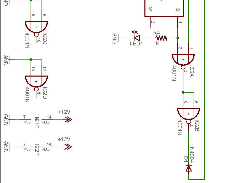
5) Switches are triggering by themselves only when mod board is in – Check Column 3 connection to CPU. Also 4001 IC may be bad.
6) The LED on the Mod Board is toggling by itself – Check IDC connectors for loose wire on Column 6 or Row 7.
7) Switch 28 “Ball on magnet” – This is normal.
Opto troubleshooting
Figure 1 - Switch Locations.
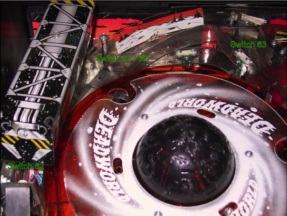
Figure 2 - Ball on ring.

Figure 3 - Right Opto Board.
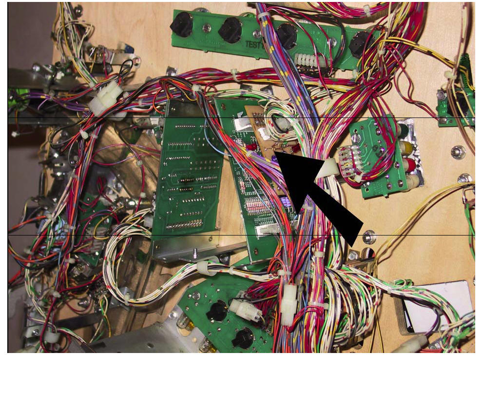
Figure 4 - CPU Board
Parts List

C1 – 100uF 25V electrolytic
C2, C3 – 0.1uF ceramic 25V
D1 – 1N4004
IC1 - CD4013 CMOS Dual D Flip Flop 14 pin DIP w/gold plated socket
IC2 - CD4001 CMOS Quad Nor 14 pin DIP w/gold plated socket
R1, R2, R3 – 10K - ¼ Watt 5%
R4 – 1K-¼ Watt 5%
R5 – 100K-¼ Watt 5%
9 pin Molex receptacle w/0.1 spacing
12 pin Molex header w/0.156 spacing
12 pin Molex receptacle w/0.156 spacing