Flashers in the Pop Bumpers
There's already a mod for the Creature out there. Here's the web page. I didn't want the resistors in there, so I took a different approach. I used the 20V flasher voltage supply, and put diodes on each line to isolate the pop bumper circuits from the flasher voltage. You can buy a kit of the difficult part from Pinbits.
The movie
Parts:
Popbumper lamp sockets 3
Diodes 1n4004 3
Wire 3 feet
Bulb, 444
3
Zener diode, 6.8V 5W 1
High brightness option
There is one unintended consequence. If the solenoid supply fuse is removed, the flasher supply bridges through the tieback diodes and gives the solenoids about 17V. Enough to make them pulse, but that is about it. If the solenoid voltage is present, there's no issue. One possible consequence is that a shorted solenoid will also blow the flasher fuse.
 Here's
the new wiring under the playfield. I used conventional tin strip pop
bumper sockets, all the holes are there. I would have tried the flexible
wire sockets, but Danny Miller warned me that they set the lamp too high
in the socket. Once is enough. Here's
the new wiring under the playfield. I used conventional tin strip pop
bumper sockets, all the holes are there. I would have tried the flexible
wire sockets, but Danny Miller warned me that they set the lamp too high
in the socket. Once is enough. |
There something else going on
here. I am putting Molex connectors on my solenoids, like the later WPC
games. Adds a few minutes this time around, but will save me time if I
go out for a clearcoat. It also makes this mod a bit easier.
|
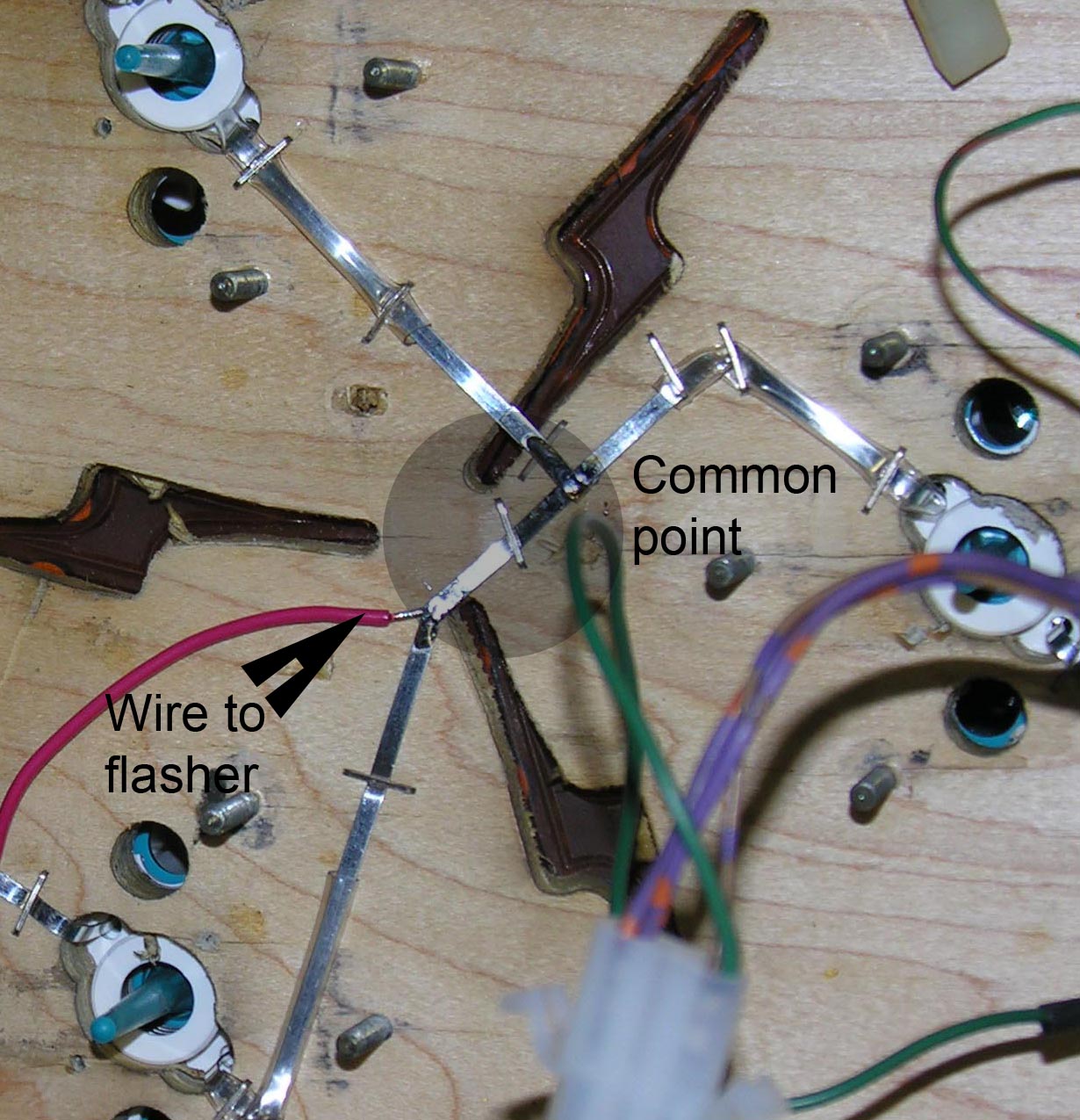 Step
1: Put in your pop bumper lights, and staple them down as you see
here. Bring the three (partly insulated) insulated wires to a common
point. Step
1: Put in your pop bumper lights, and staple them down as you see
here. Bring the three (partly insulated) insulated wires to a common
point.
Make sure to avoid the places where the brackets will go. |
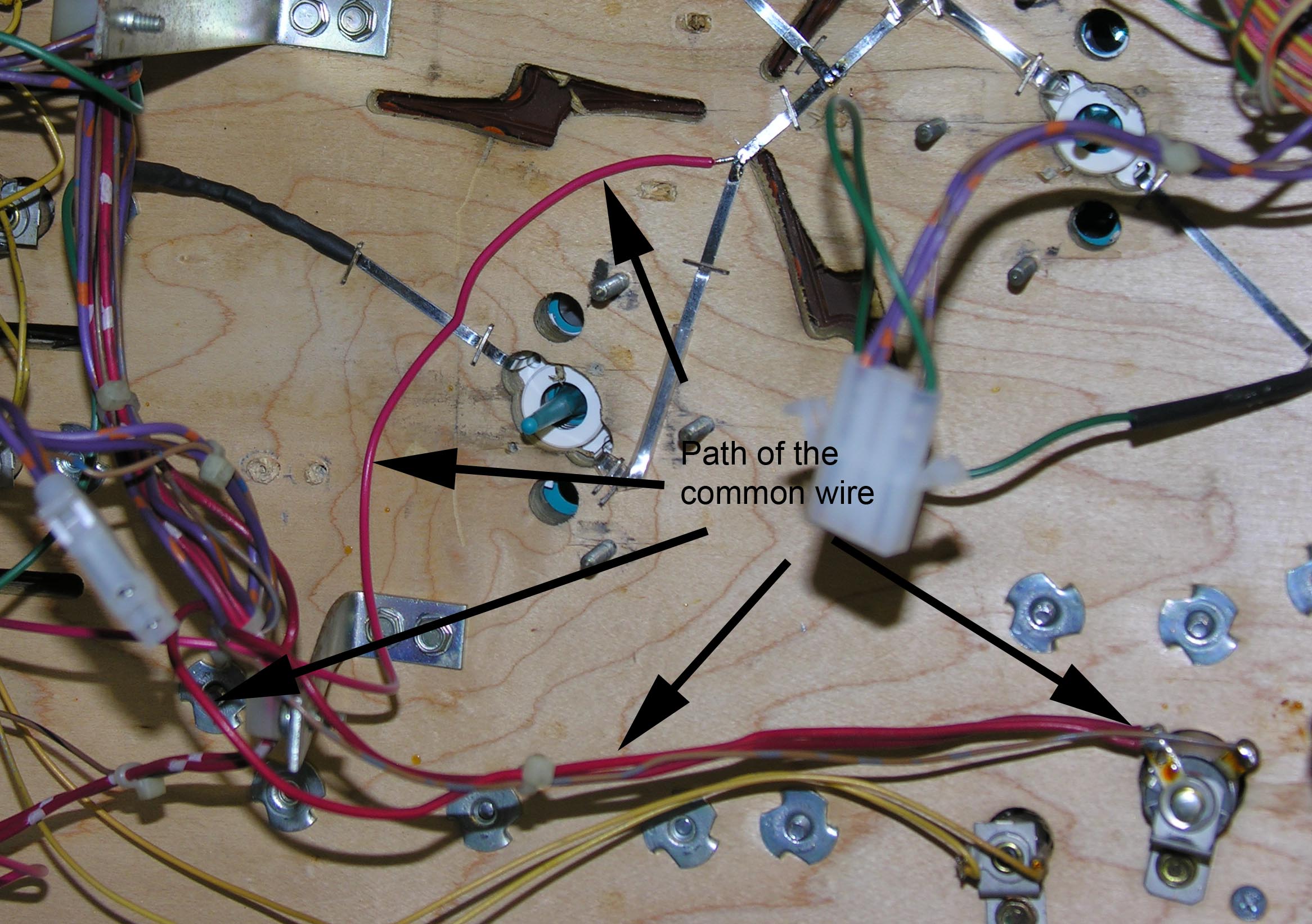 Step
2: Solder a wire to the common point, and run it to the
flasher at the bottom right of the machine. Run it with the existing
loom. Step
2: Solder a wire to the common point, and run it to the
flasher at the bottom right of the machine. Run it with the existing
loom.
Step 3:
|
 Step
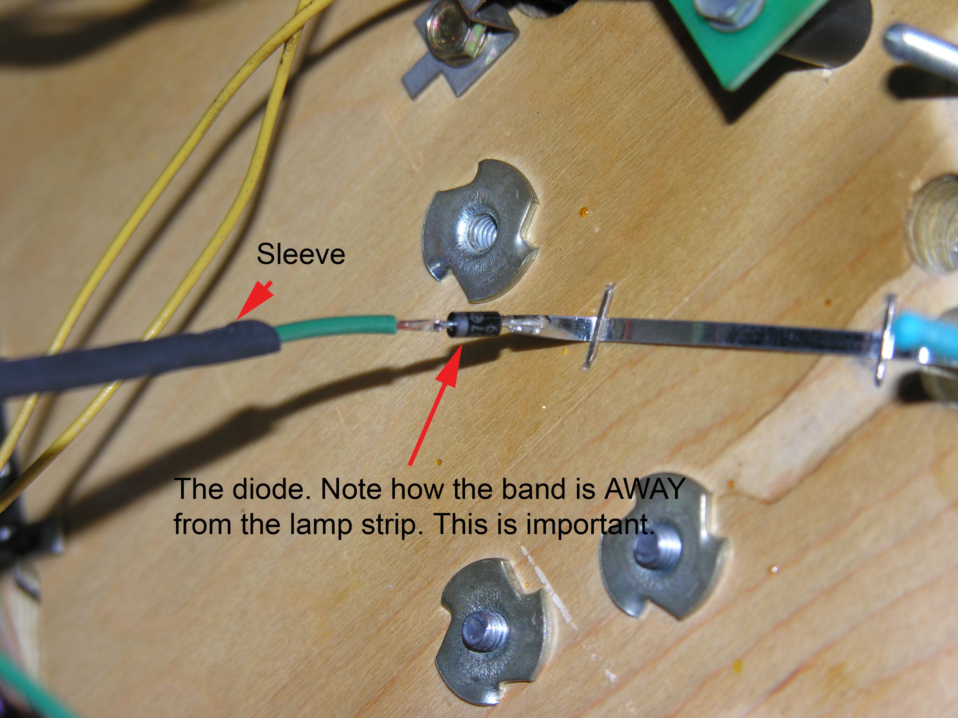
4: Add a diode, banded end away, to each of the three remaining
ends. I trimmed the ends a bit. The diode leads were about 1/4" long. Step
4: Add a diode, banded end away, to each of the three remaining
ends. I trimmed the ends a bit. The diode leads were about 1/4" long. |
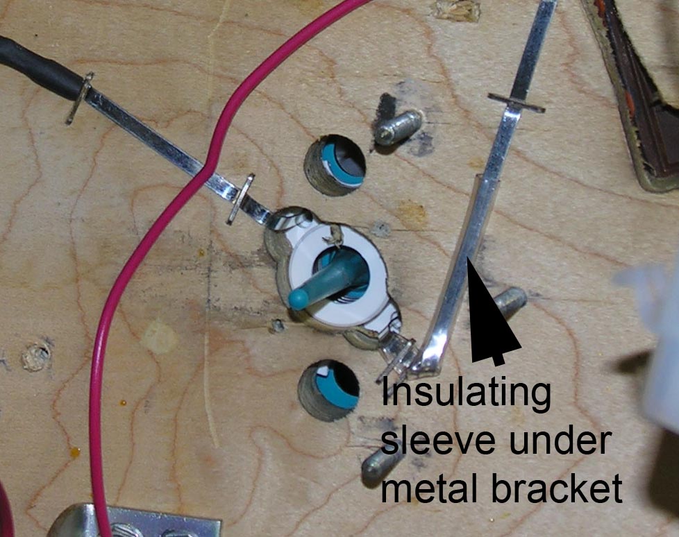
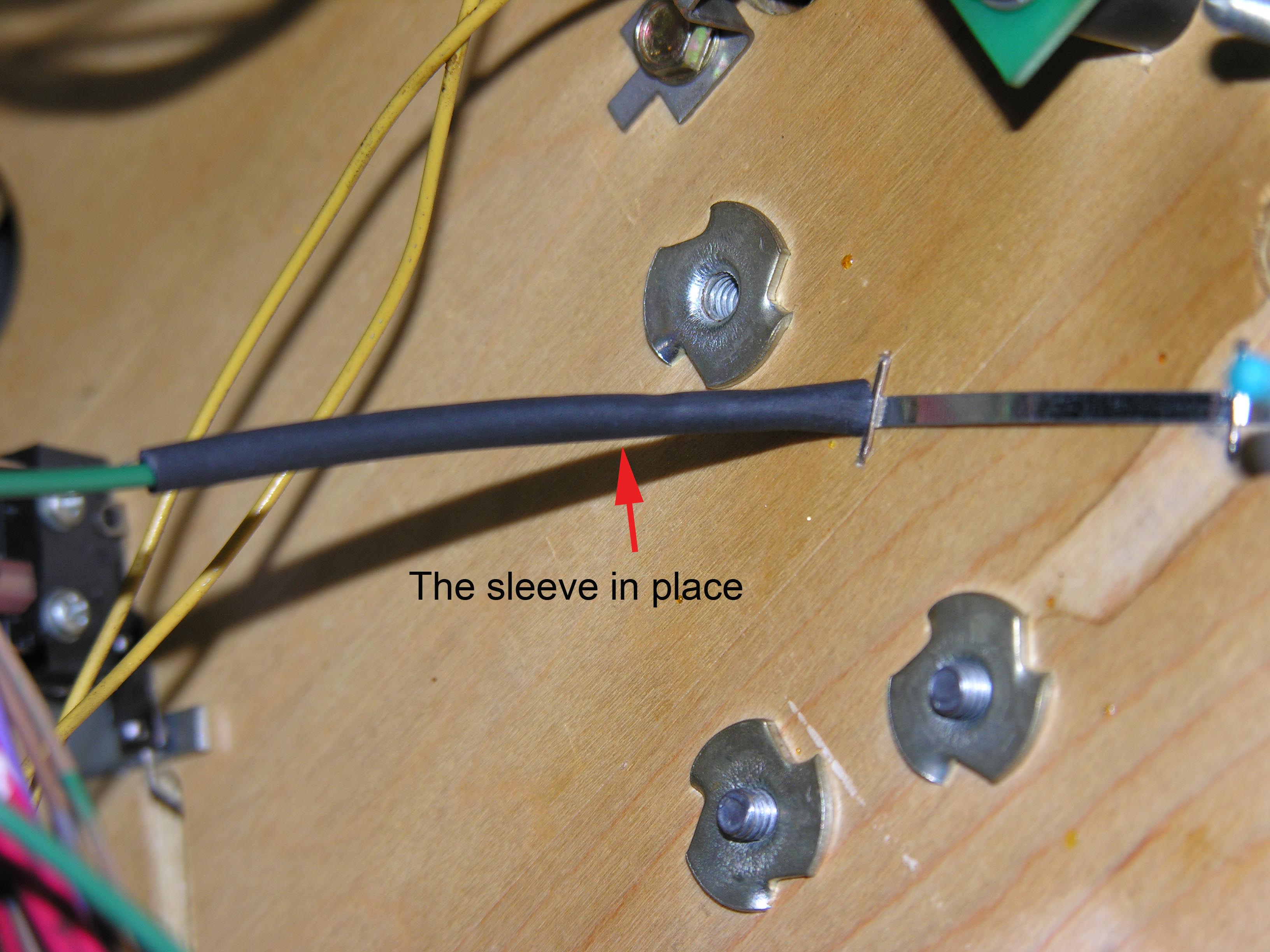 Step
5: Put about 1.5" of heat shrink on a piece of wire, and solder it
to the other end of the diode. When everything cools down, slide
the heatshrink over the diode and the flat wire. Step
5: Put about 1.5" of heat shrink on a piece of wire, and solder it
to the other end of the diode. When everything cools down, slide
the heatshrink over the diode and the flat wire. |
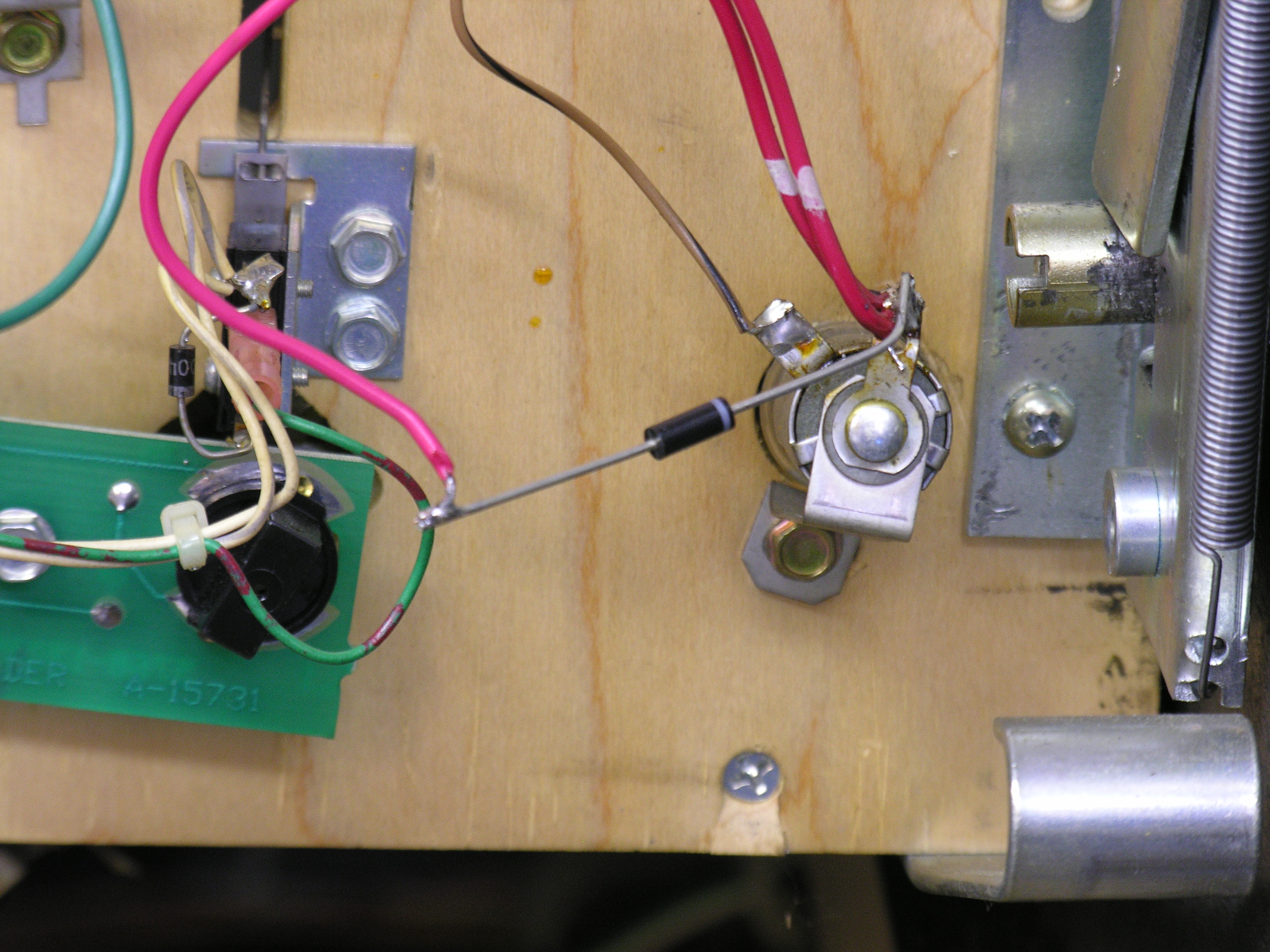
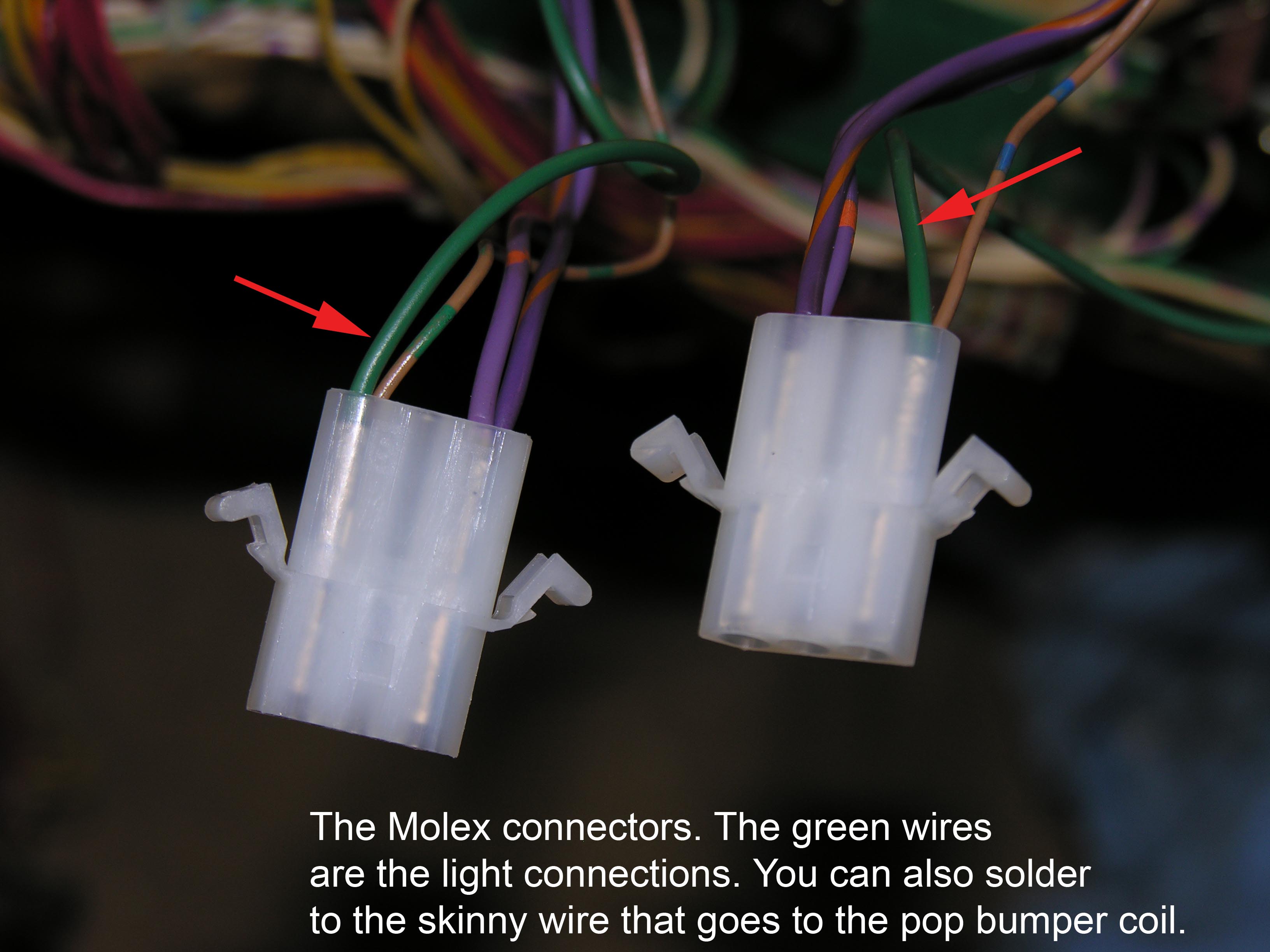 Step
5: Run the other end of the wire to the skinny wire (usually
brown/something) that attaches to
the corresponding pop bumper coil. I did this in the Molex connectors
that I installed. It helps to tie the new wire to the existing wire with
a cable tie if you are soldering direct to the coil connections.You are done with the mods. Step
5: Run the other end of the wire to the skinny wire (usually
brown/something) that attaches to
the corresponding pop bumper coil. I did this in the Molex connectors
that I installed. It helps to tie the new wire to the existing wire with
a cable tie if you are soldering direct to the coil connections.You are done with the mods. |
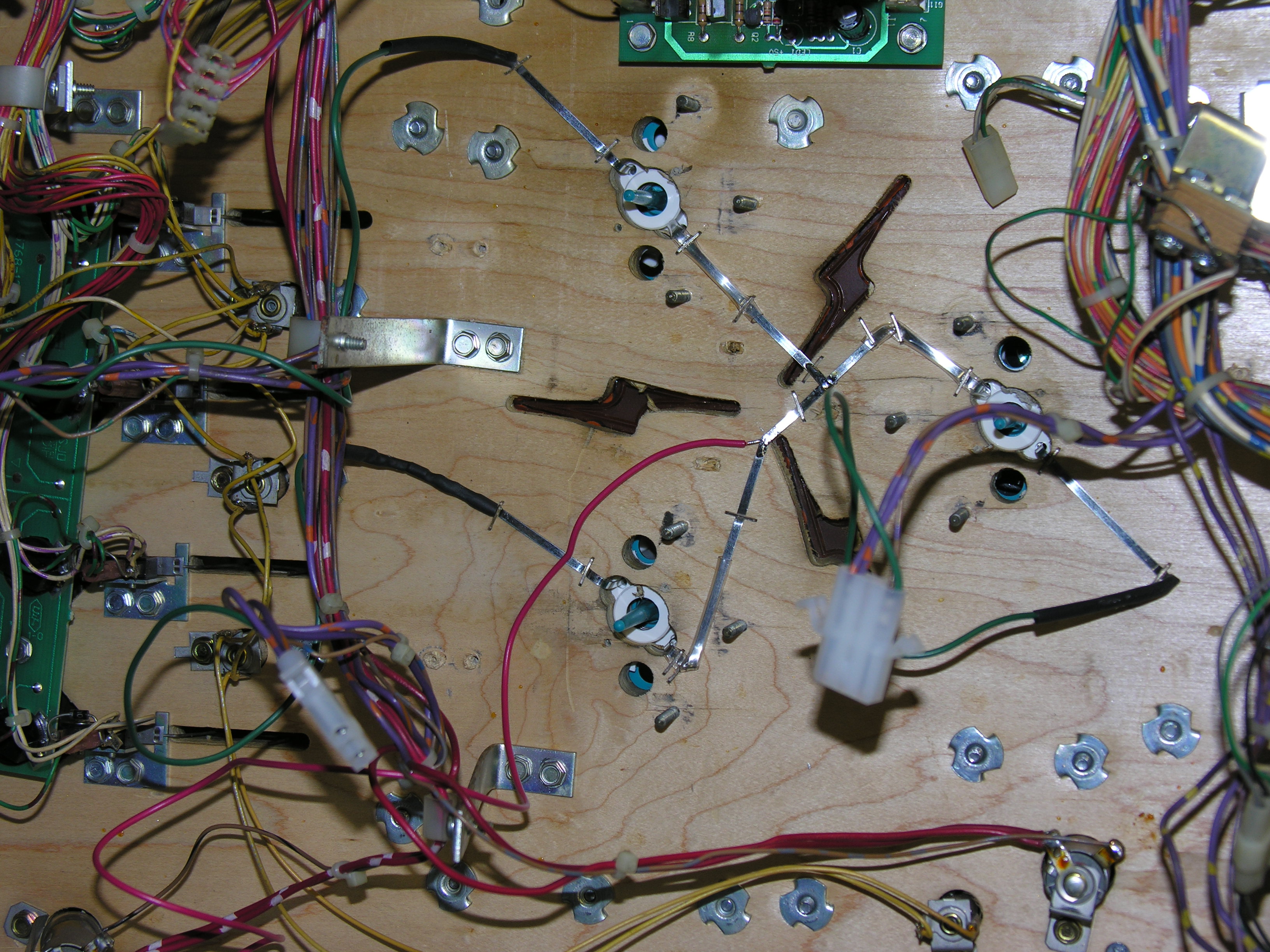
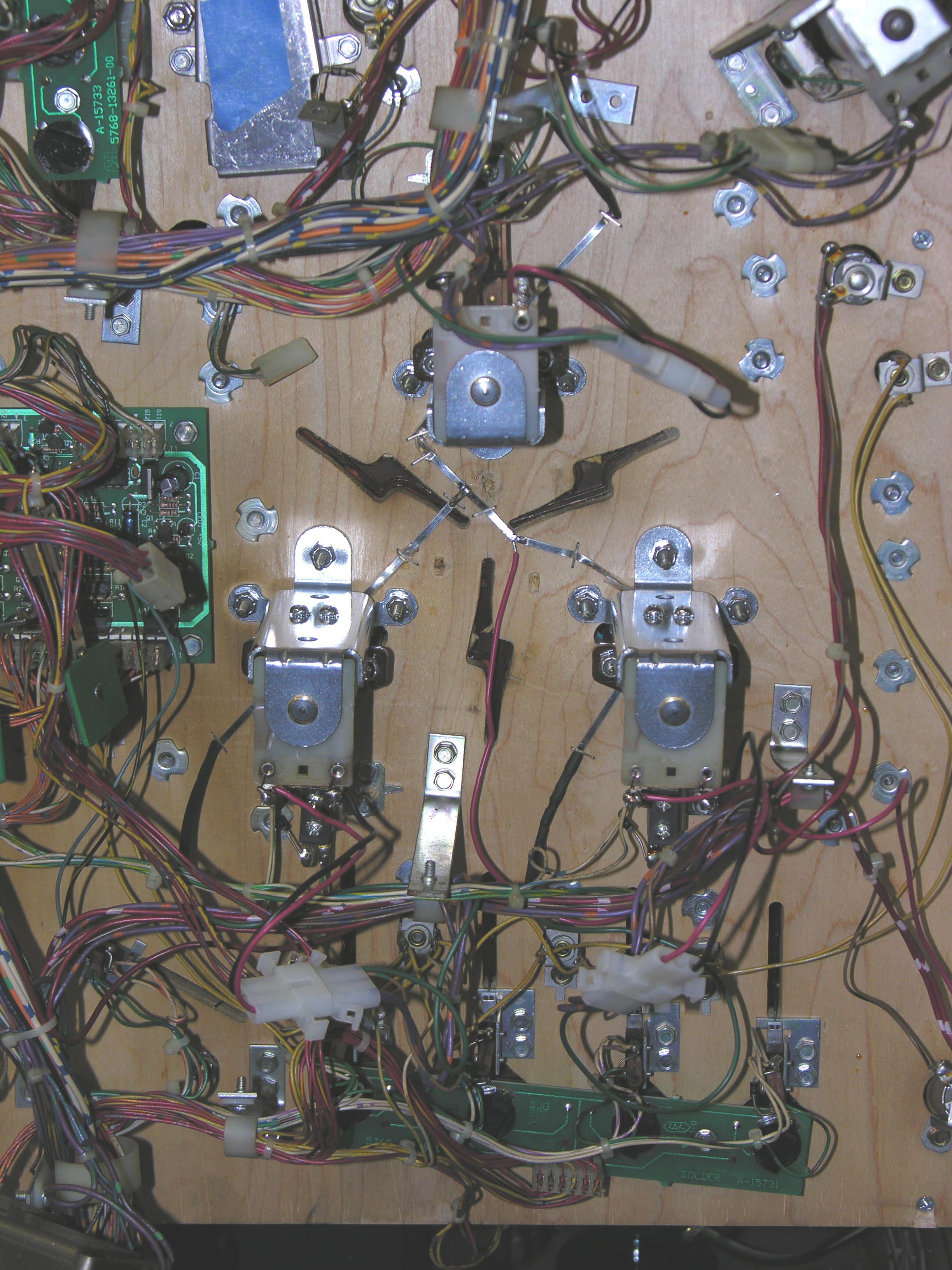 The
final assembly, before wire dressing and replacement of the board. Next
time, I would not cross the wire over the lightning bolt - the insert
will be hard to clean. The
final assembly, before wire dressing and replacement of the board. Next
time, I would not cross the wire over the lightning bolt - the insert
will be hard to clean. |
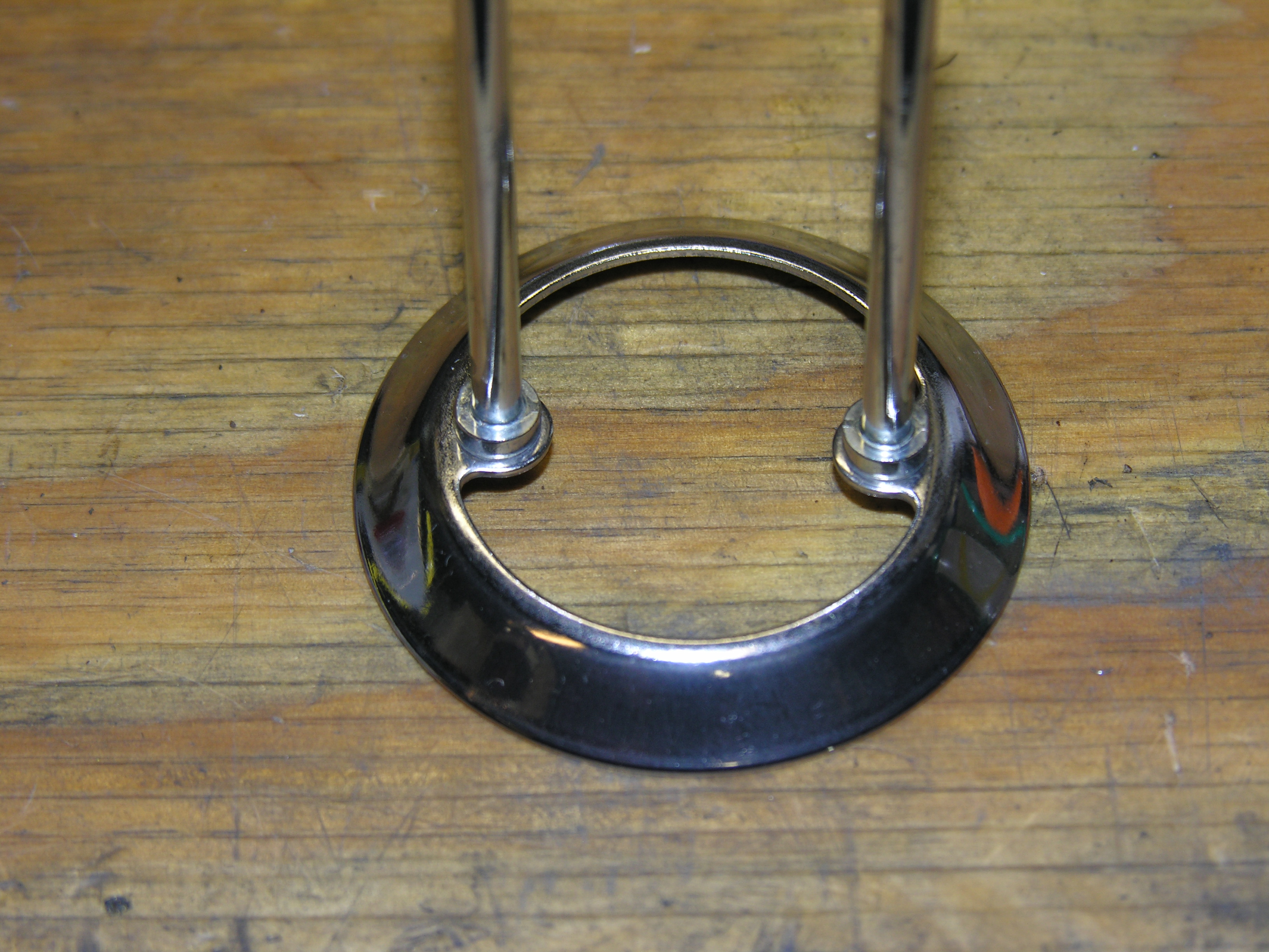 Trivia:
the old pop bumper rings are much smoother than the new ones. I don't
have a new one to show here, but here's an old one with its mirror-like
finish. The new ones have little grooves in them. Trivia:
the old pop bumper rings are much smoother than the new ones. I don't
have a new one to show here, but here's an old one with its mirror-like
finish. The new ones have little grooves in them. |
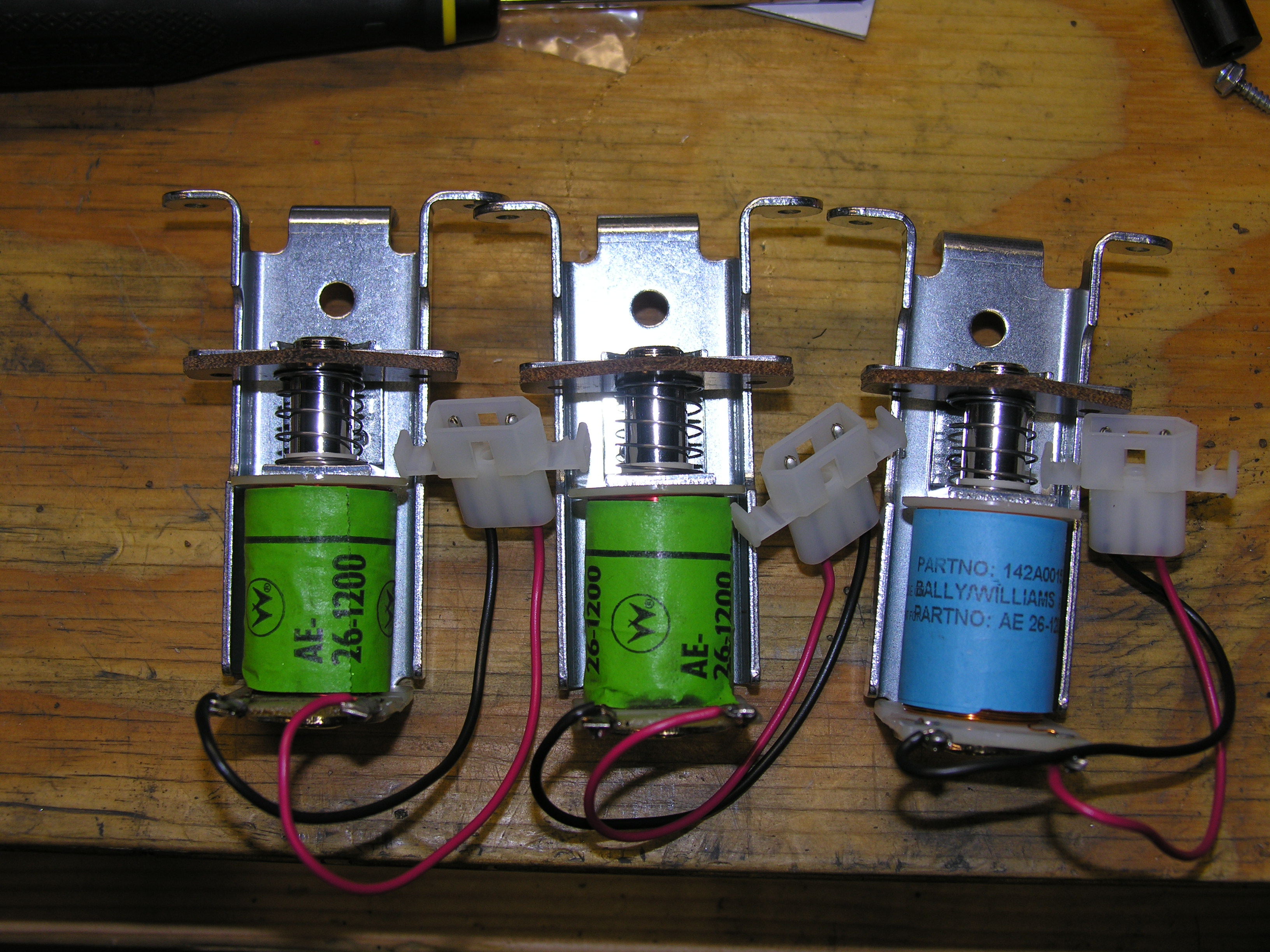 My
modified pop bumper assemblies, awaiting assembly into the machine. They
have been through the tumbler or ultrasonics. My
modified pop bumper assemblies, awaiting assembly into the machine. They
have been through the tumbler or ultrasonics. |
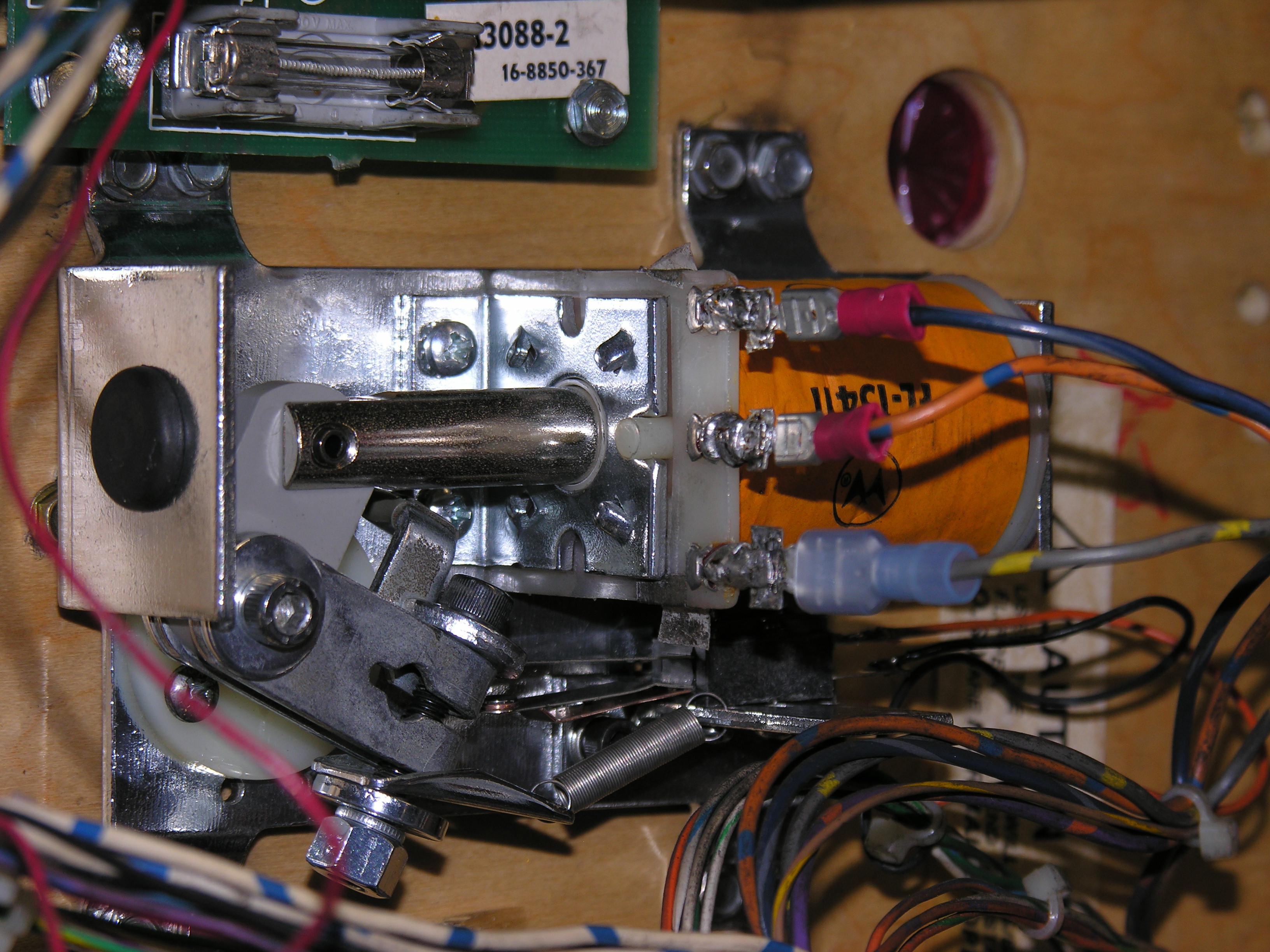 I
replaced the right flipper coil (1129) with a new one with push tabs, so
I put push tabs on the wire. I like that enough to do the same thing to
the left. The tabs came from opened-up crimp connectors. And yes, the
hold and flip are reversed in this photo. I
replaced the right flipper coil (1129) with a new one with push tabs, so
I put push tabs on the wire. I like that enough to do the same thing to
the left. The tabs came from opened-up crimp connectors. And yes, the
hold and flip are reversed in this photo. |
|