 I
have identified a good source for alternate trigger transformers. These parts
work well in this application, and should be more robust than the originals.
Here's a picture of how to install one of these. We have them up on Pinbits.
I
have identified a good source for alternate trigger transformers. These parts
work well in this application, and should be more robust than the originals.
Here's a picture of how to install one of these. We have them up on Pinbits. Fixing the AFM Strobe Board
John I. has done a great job with his guide to the AFM strobe board, and his troubleshooting process. It has most of what you need to know to debug a non-working strobe board, but I have a few more things to cover.
Before we start, though, this board is DANGEROUS. It boosts the 50VAC line up to 300VDC for the flash, and stores a fair amount of energy. As in, the board can be dangerous even if it isn't wired up. The capacitors can dump about 100A into the flashtube. Think defibrillators. It also cracks up about 4,000V to fire the flashtube. Stay away from that as well.
I
have identified a good source for alternate trigger transformers. These parts
work well in this application, and should be more robust than the originals.
Here's a picture of how to install one of these. We have them up on Pinbits.
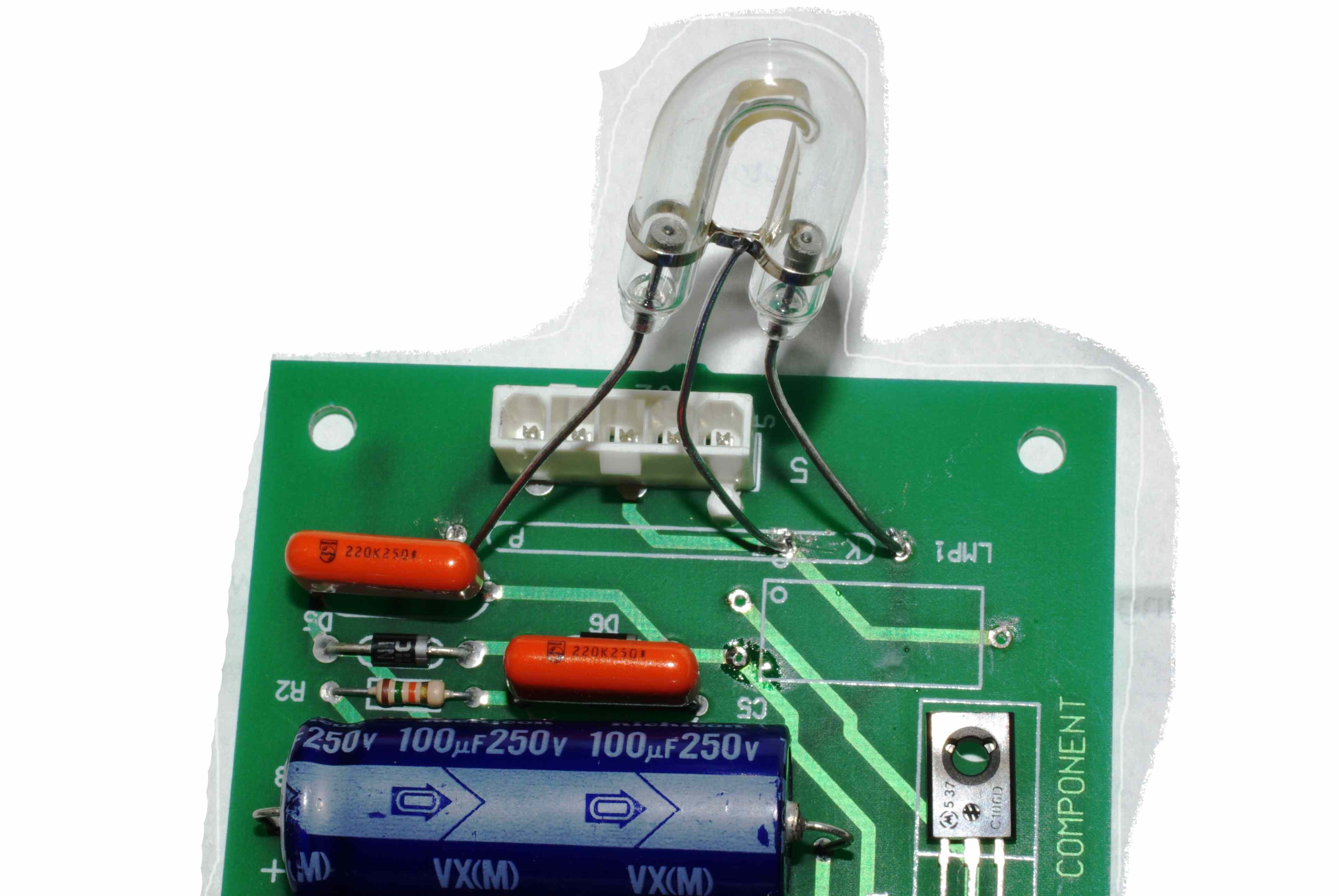
The Williams flashtube is a special low-pressure tube that can trigger at
150V. This is important, as the storage capacitors only have time to charge to
this level during strobe multiball. An incorrect tube will run at half speed or
less. This is a common AFM problem, it seems. I am working on a way to mount a
horseshoe tube. Here's the prototype.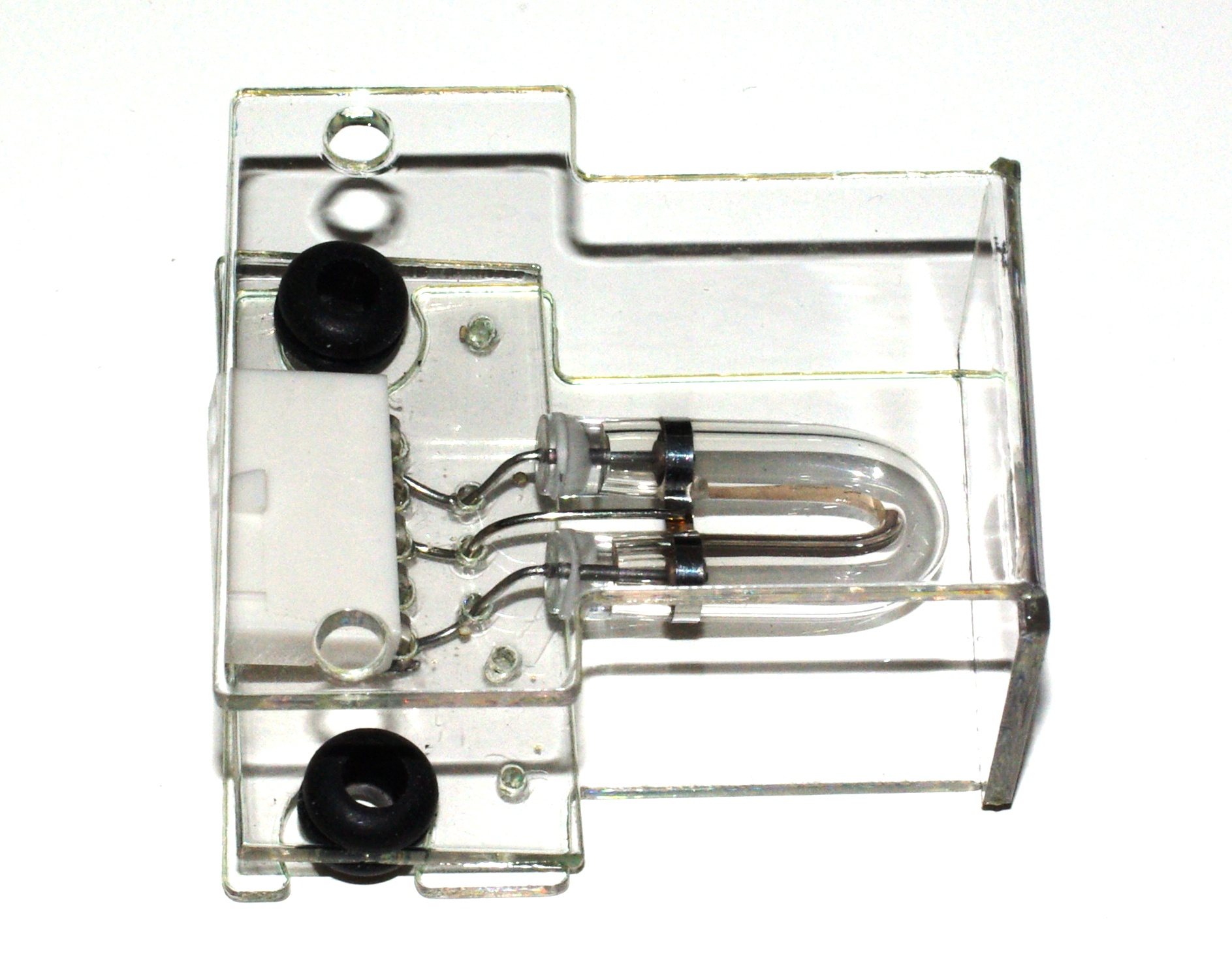 The real thing lines up with the tube in the middle of its shield, it is
front-heavy in the picture. The shield is PETG. The PCB is a PETG model.
The real thing lines up with the tube in the middle of its shield, it is
front-heavy in the picture. The shield is PETG. The PCB is a PETG model.
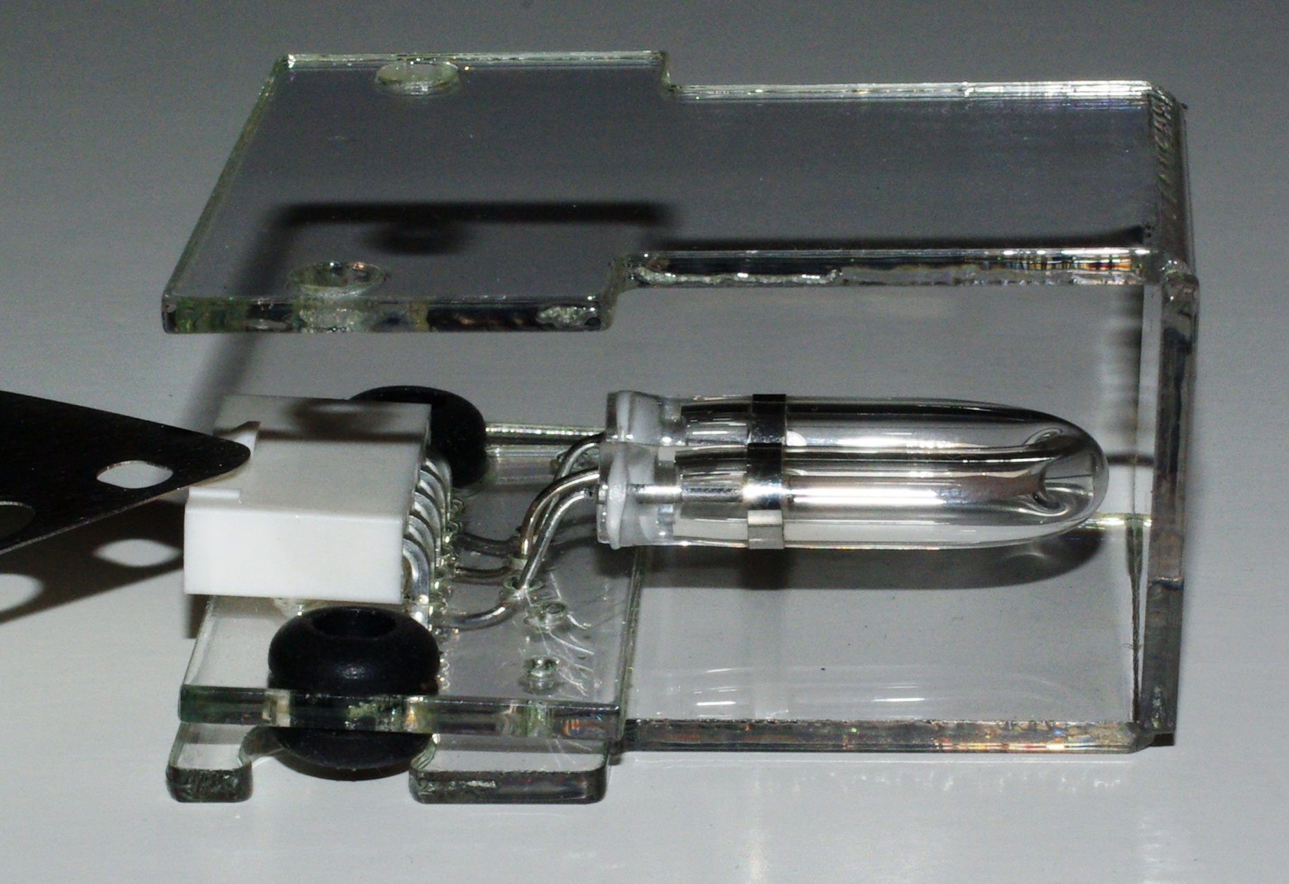 The
shield will work with the tube mounted to the original board.
The
shield will work with the tube mounted to the original board.
Troubleshooting Notes.
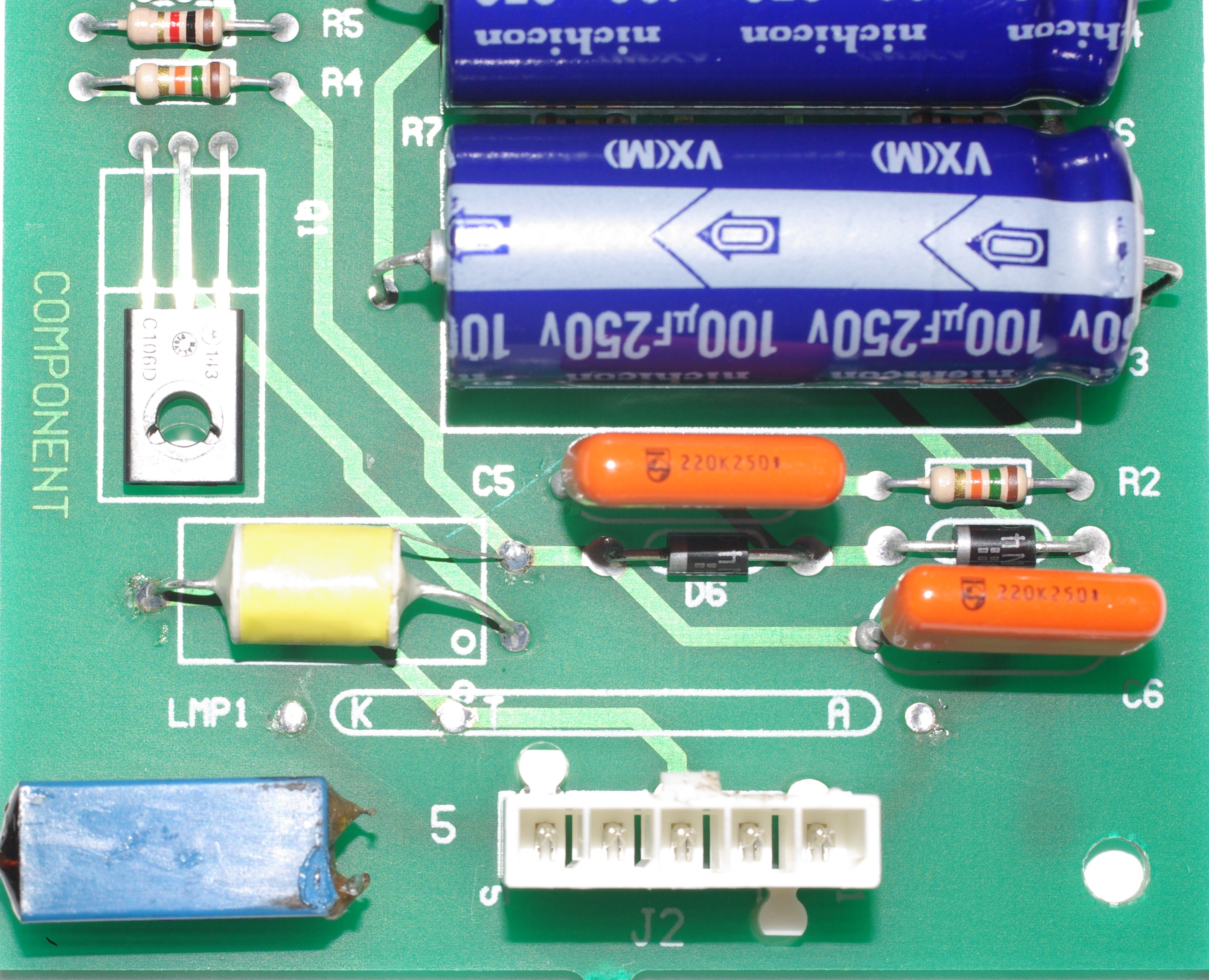
First, use John's document to make sure that you have all the correct voltages, and that the solder joints, diodes, resistors and capacitors are good. 250 - 300V across the big caps is a good sign that all is well in this department.
The board's design is such that C1 always has 140V across it. The part is rated at 100V. Therefore, it is always 40% overloaded. It responds to this treatment by swelling, leaking and giving up all pretense of being a capacitor. AFM strobe boards are therefore guaranteed to stop working. My limited experience shows that C2 and the 250V caps are usually OK.
I received a board that worked, but blew the ULN2803 driver on the WPC power-driver board. This failure could be caused by either excess current through the opto circuit, or some high-voltage leakage. Neither seems particularly likely, as the isolation gaps are quite good.
However, I did find one thing. The large ceramic resistor had been resoldered,
and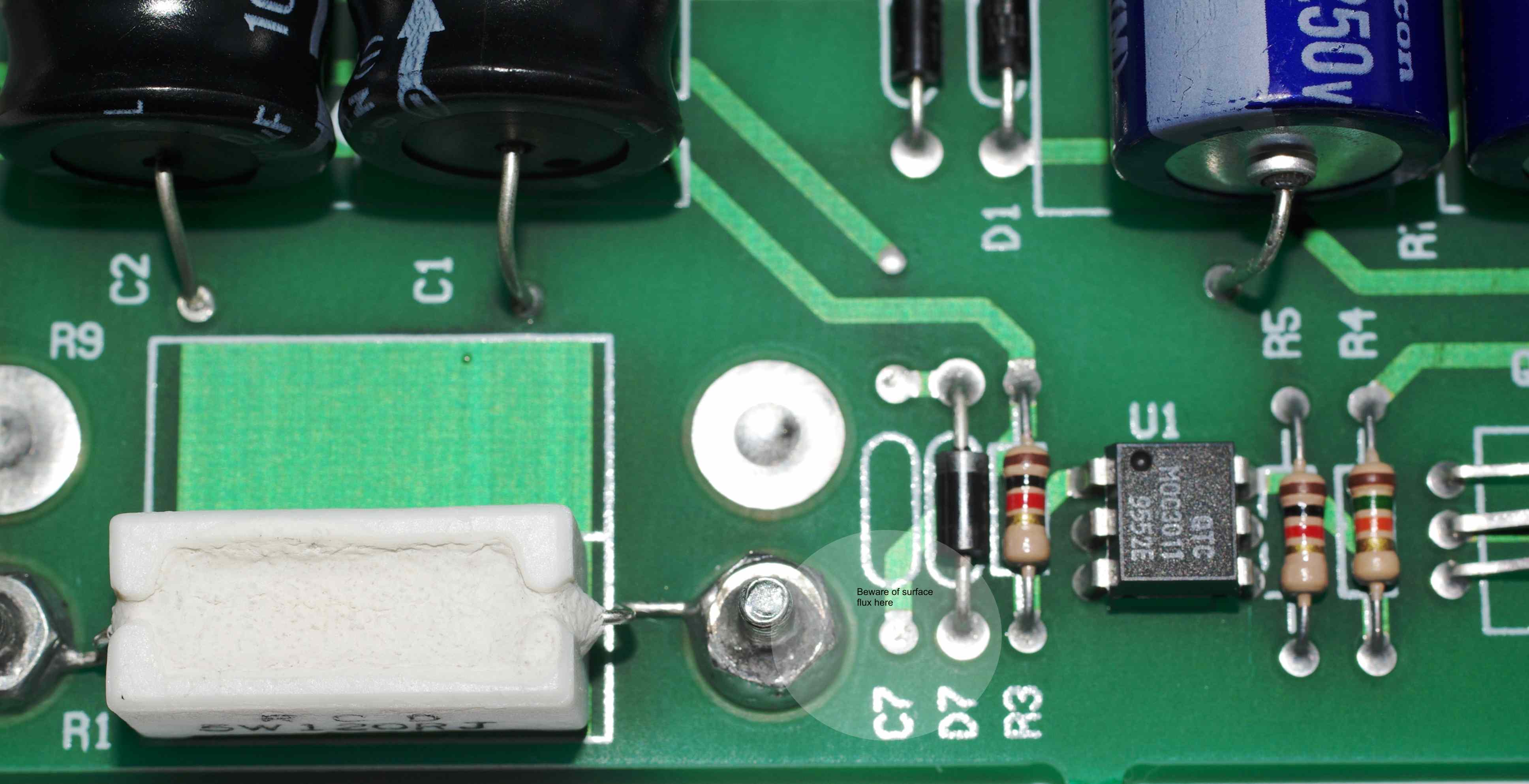 there was flux residue between the right hand terminal and the empty pad for C7.
This flux was bridging the high voltage and low voltage circuits. It normally is
not a problem, but a bit of humidity and the high working voltages could result
in high-energy pulses getting back into the driver circuit. After cleaning this
up and replacing the trigger transformer, the owner reported that the problem
was fixed.
there was flux residue between the right hand terminal and the empty pad for C7.
This flux was bridging the high voltage and low voltage circuits. It normally is
not a problem, but a bit of humidity and the high working voltages could result
in high-energy pulses getting back into the driver circuit. After cleaning this
up and replacing the trigger transformer, the owner reported that the problem
was fixed.
The moral of the story is, scrub the board squeaky clean when you are done. Use an aggressive cleaner like Mean Green or Greased Lightning and a medium stiff nylon brush. Follow up with hot water and a really good drying. The board should look clean when done.
 Next,
there a a few tricks you can try for bench testing the board. I soldered an
inexpensive horseshoe flash tube directly to the board for testing. I did this
because I did not have a flash board.
Next,
there a a few tricks you can try for bench testing the board. I soldered an
inexpensive horseshoe flash tube directly to the board for testing. I did this
because I did not have a flash board.
To trigger the flash, use an insulated handle screwdriver and short its blade across the top two leads of the triac. This is safe for the circuit, but stay away from the metal! There should be a tiny spark (yes, there's 100 - 200V here) and a bright flash from the tube. If this does not happen, then either your transformer is open circuit (most likely); your triac is shorted; or your opto is shorted. Measure the DC voltage across those leads; if it is very low, you have a shorted triac. If high, an open transformer.
The next thing to short is the output of the optoisolator. This is pins 4 and 6 - the top and bottom pins on the right hand side. If these pins fail to create a flash, then you have either a shorted opto or a defective triac.
The opto also goes open circuit. If shorting the pins on the output causes a flash, but the driver circuit does not work, then you should replace the opto.
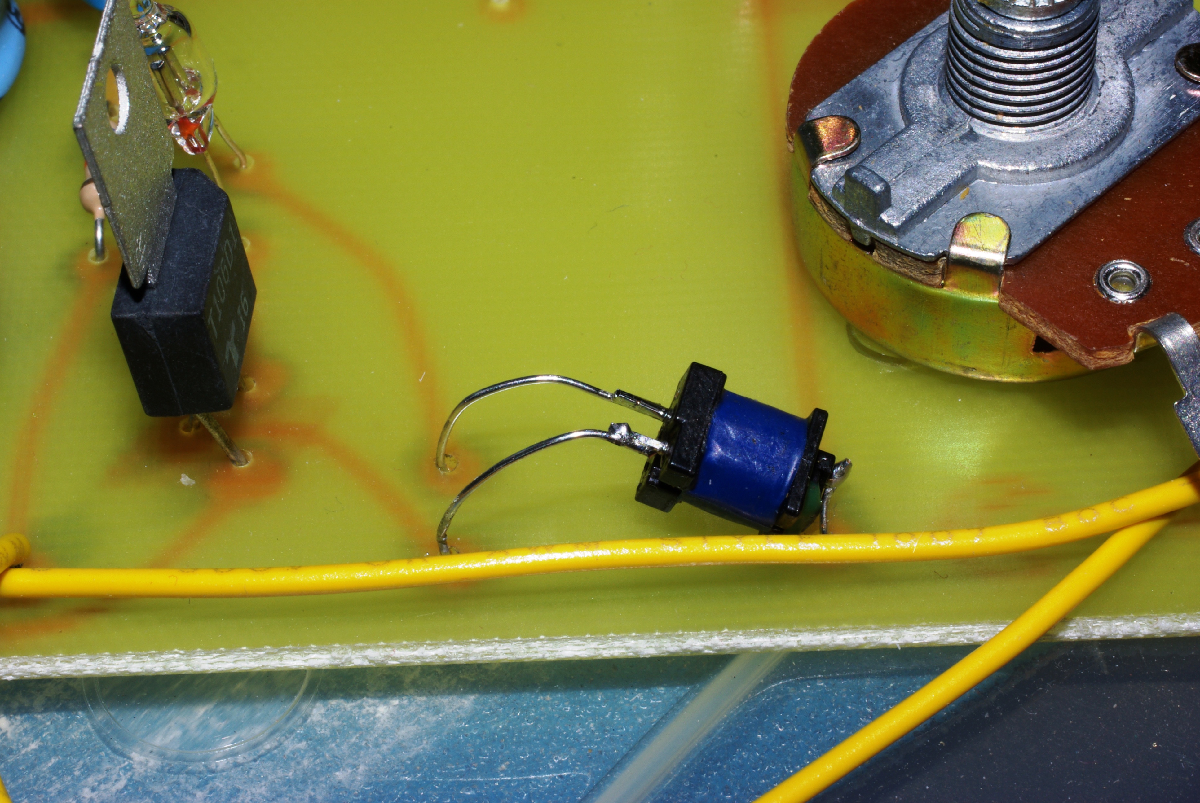 You
can use a transformer from a disposable camera in this circuit. Here's one
sitting on my test board. They are delicate, but will work in a pinch. This one
is happily driving a big horseshoe tube. I have identified and tested an
appropriate replacement trigger transformer; we have them for sale on Pinbits in
our
AFM section.
You
can use a transformer from a disposable camera in this circuit. Here's one
sitting on my test board. They are delicate, but will work in a pinch. This one
is happily driving a big horseshoe tube. I have identified and tested an
appropriate replacement trigger transformer; we have them for sale on Pinbits in
our
AFM section.
Tip: When done, separate the four large electrolytic capacitors so that they don't touch. The air gap will allow them to cool a little better,
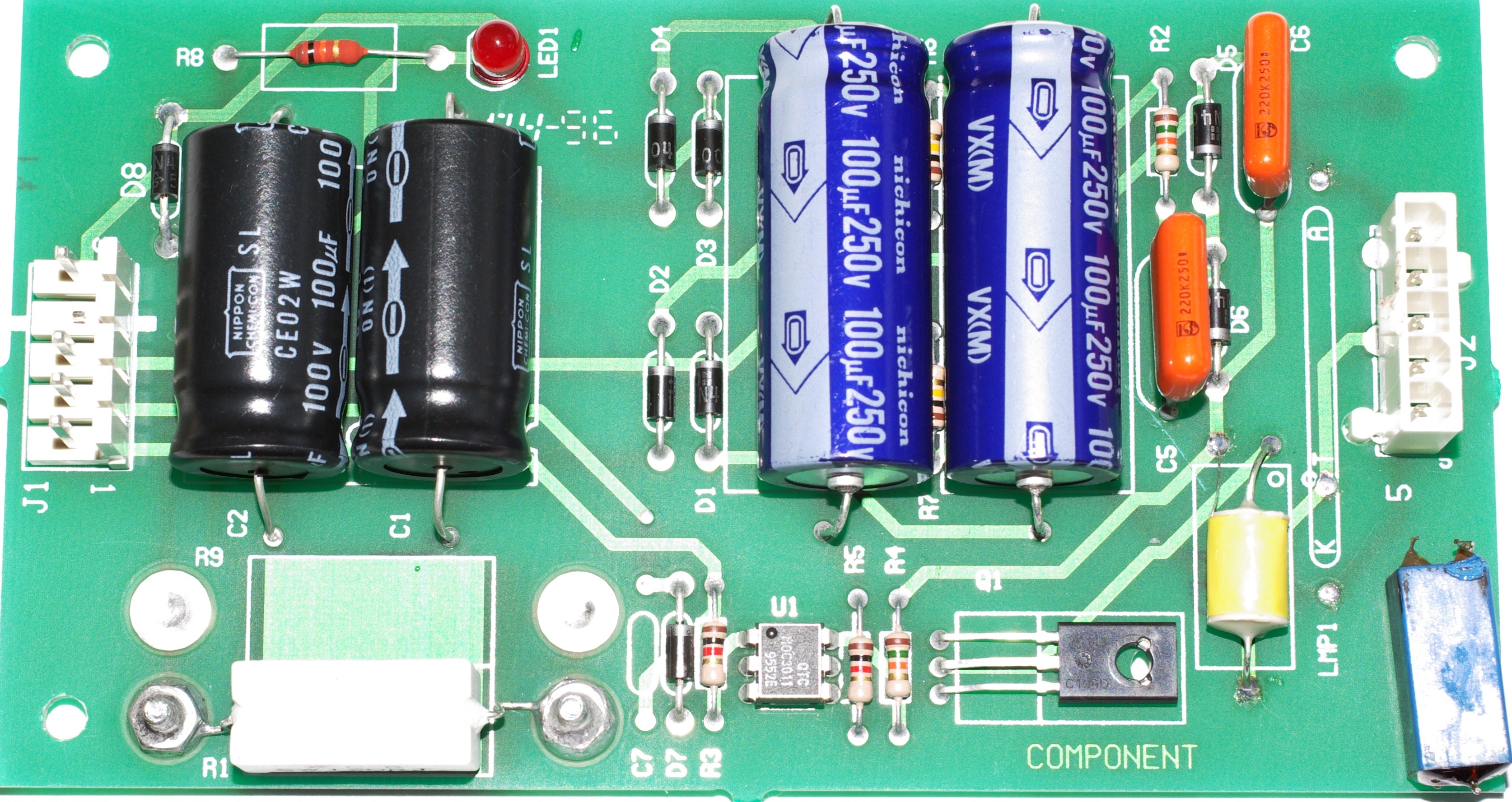
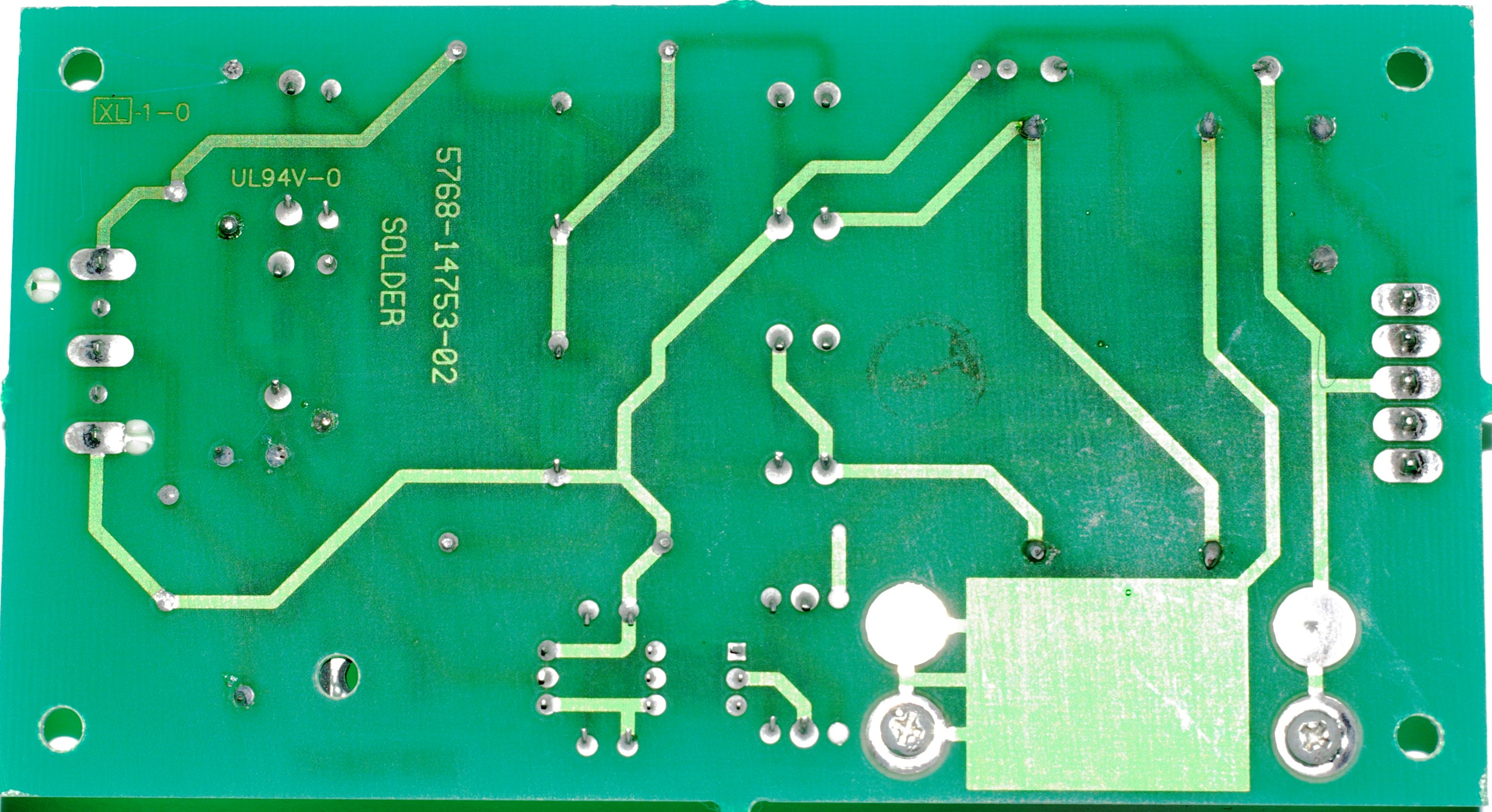 Pictures
of the top and bottom sides of the board for the records. You can see a
replacement trigger transformer on this board.
Pictures
of the top and bottom sides of the board for the records. You can see a
replacement trigger transformer on this board.