The Applied Microsystems EM189 Emulator
This is a neat piece of equipment that really helps with fixing 6809 based stuff. They are quite rare, but occasionally turn up on eBay. I have one with a working 6809 pod, and a non-working 6809E pod. Actually, the 6809E pod doesn't work in a WPC socket (see notes), but seems fine elsewhere.
Here's a high-res scan of the 6809E pod boards. The trace side is mirrored, so that you can look at it as aligned with the component side.
6809/6809E Version User Manual
Z80 Version User Manual
Z80 Version Service Manual
(will give you an idea of what is what)
The April 1983 pricelist, with a bunch of marketing info
ROM image A and ROM image B from bitsavers.org ( and they have other AMC stuff)
ROM 0 and ROM
1 from my machine - these are 2764s. Rom 1C000 has a bit more code than ROM B.
It is a couple of hundred bytes at the end of the ROM, so it is probably a patch
of some kind. The rest of the ROMs are pretty similar.
6809E Programmer's Guide
6809E Datasheet
How Does It Work?
The key is that the pod processor is the brains of the unit. There's no processor in the console: all the control code runs in the pod. The pod uses NMI to hijack the processor into its own memory space, and from there it runs various access and control routines.
So you can think of the console and pod as a bunch of extra circuitry added to the target, and some code that can run when the target isn't in control. Neat.
The emulation pod has two sets of buffers, and some control logic. One set drives the address and data bus to the target, and the other set drives the buses to the console. The data bus is bidirectional, the address bus is one-way. If the console wants something from the target memory, the pod processor gets it directly.
When in run mode, the processor is buffered directly to the target signals. The console gets to watch the buses. For example, to detect a breakpoint. It can also switch the data bus to console to read from the memory overlay instead of the target system.
When the console wants control, it pulls the NMI line and switches the processor to the console address and data buses. The NMI is serviced from the console. Presumably, the NMI first saves state in console RAM, and then runs the console program.
The console program can manipulate the breakpoint registers, and also run target manipulation routines in the pod to get at target memory and I/O.
The user-generated code section of the manual has lots of useful information about peripherals and addresses in the console
Memory Map as Published
0000 - BFFF Internal RAM overlay
C000 - DFFF Disassembler
D000 - DFFF Console diagnostic ROM (2732 for all
space)
EB00 - EBFF Control registers
EC00- F000 Scratchpad
F000 - FFFF Control code
Of course, this map is for 2732s, but the machine has 2764s in it. I used introspection mode (code F5 on the console) to get to the real memory map.
ROM 0: C000 - CFFF; F000 - FFFF
ROM 1: A000 - BFFF
ROM 0 appears to be the disassembler and the control code. ROM 1 contains comments such as "single-line assembler" and I wonder if it contains more sophisticated code for serial port use.
I had a chance to chat to Tim Nelson, the designer. Here are some of my notes.
Construction Notes
The pod has four mounting screws for the PCB that have heads hidden under the label. I was able to grip the thread with pliers, and work the nuts off. I superglued them back to make work a little easier.
The console has four main segments:
Power supply - a nice traditional AC transformer power supply with series pass 2N3055s for 12V and 5V.
Keyboard - keyboard, control ROMs, local RAM. The pod processor executes off
of this board. It is both a peripheral and main console memory.
Display board - 7-segment displays, memory buffer and LEDs. This is an output
peripheral.
Main board - trace logic, buffering, all the other neat stuff.
There's also a serial UART upgrade, and a RAM overlay that allows target memory to be substituted out.
 Here's
the keyboard module. This board also carries the code ROM and scratch
RAM. Here's
the keyboard module. This board also carries the code ROM and scratch
RAM. |
 The
RAM expansion board. 64k of overlay ram that can replace ROM in the
target. This was a $2,700 option. The whole system was only $3,750. But
of course, the RAM made a huge difference - no need to burn EPROMS! The
RAM expansion board. 64k of overlay ram that can replace ROM in the
target. This was a $2,700 option. The whole system was only $3,750. But
of course, the RAM made a huge difference - no need to burn EPROMS! |
 The
serial option board. Not much to see. This was standard on the machine
by 1983. The
serial option board. Not much to see. This was standard on the machine
by 1983. |
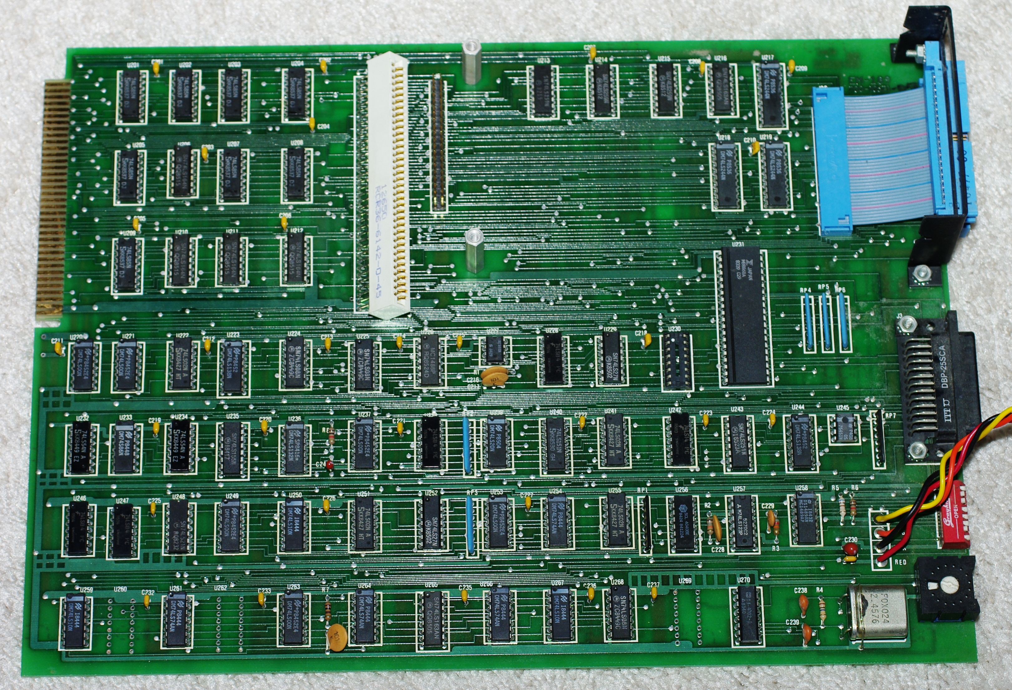 The
main board. All of the interfaces, the breakpoint comparisons, the trace
buffer and a bunch of other random logic and connectors. The
main board. All of the interfaces, the breakpoint comparisons, the trace
buffer and a bunch of other random logic and connectors. |
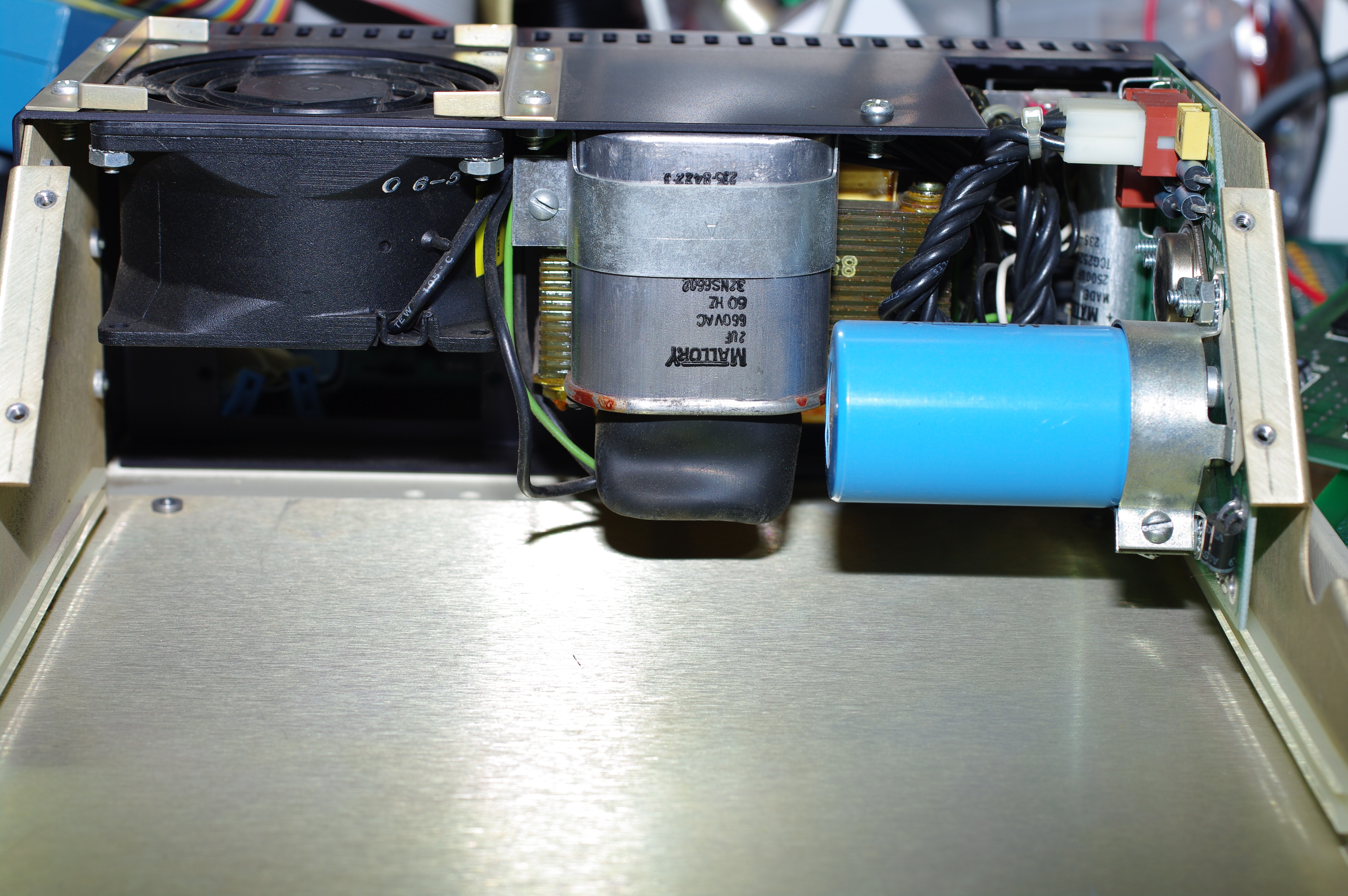 The
chassis, showing the linear power supply. The
chassis, showing the linear power supply. |
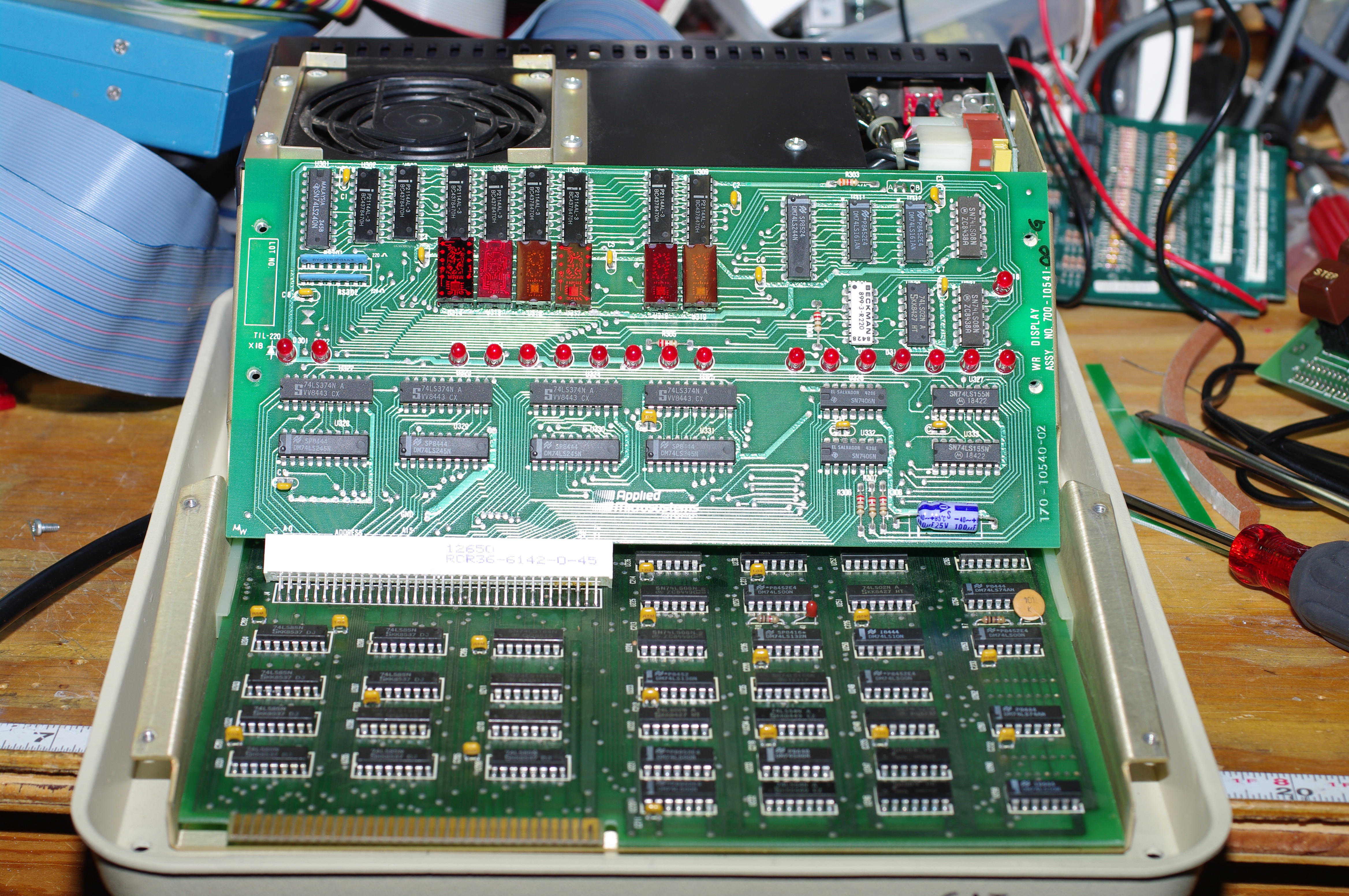 With
the main board and display board inserted. With
the main board and display board inserted. |
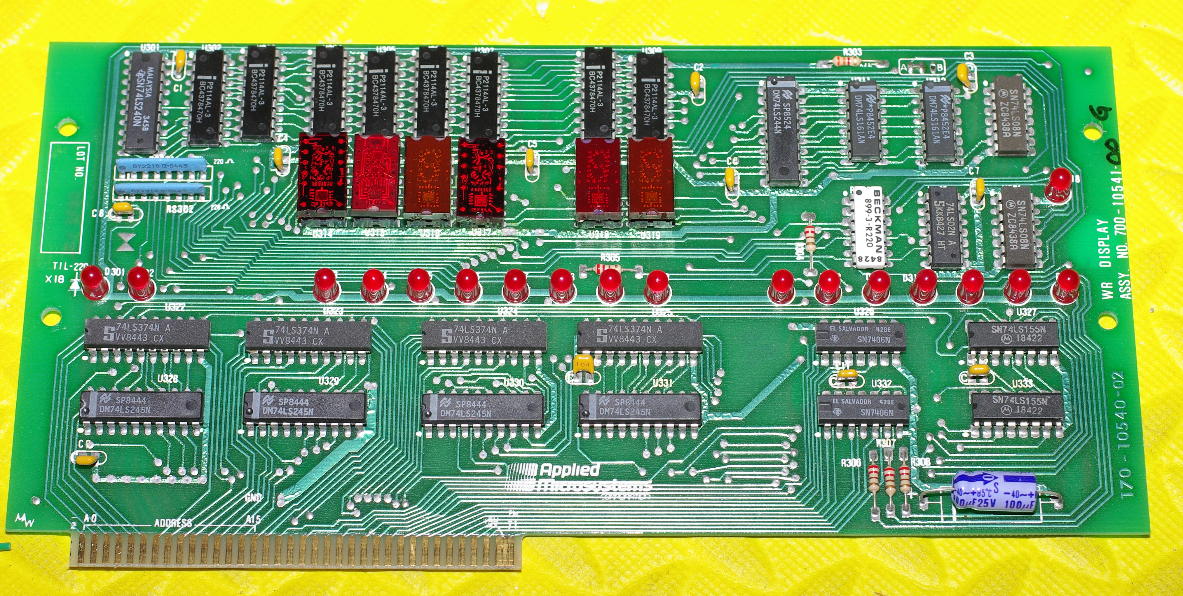 The
display board. Note the multiple different types of LED. Makes me think
that some had failed in the past. Update: the seller confirmed this.
Apparently, these things run hot and occasionally fail. The
display board. Note the multiple different types of LED. Makes me think
that some had failed in the past. Update: the seller confirmed this.
Apparently, these things run hot and occasionally fail. |
|
Exceptions: Watchdogs and Interrupts
Warning: Spent all day trying to get the 6809 pod to work on a WPC pinball controller. It doesn't. The pod will run the target, but the pod doesn't run the console code. For example, the address keys only affect the first digit, unless you press them simultaneously. I stacked an emulator into the pod, and found that I could not reliably test the system memory at EC00. No problem in the 6809 socket of a WPC sound card. So there's something funny about the WPC 6809 socket. I suspect the clock and the WPC ASIC.
Update. The problem is the watchdog circuit. This thing trips really fast - I'd guess every 10 milliseconds. When it trips, it resets the ASIC and the processor, and the emulator responds to the reset. So nothing works very well, because the board streams resets to the emulator. My first workaround was to cut the reset pin on my adapter stack, and pull the reset high. Now, the emulator works, but as soon as execution halts, the watchdog resets the ASIC. As soon at that happens, the software goes through the restart routine. Fixing this will be tricky, unless I can figure out how to disable the watchdog inside the ASIC.
The solution turns out to be to use the watchdog disable jumper on the CPU. I'll need some run-to-pause code to clear the outputs for machine test, or I'll be smoking solenoids and flashers.
There's an option on the EM189 to disable external resets from affecting the console. However, this option does not prevent the deluge of watchdog resets from jamming the machine.
The solution turns out to be to use the watchdog disable jumper on the CPU. I'll need some run-to-pause code to clear the outputs for machine test, or I'll be smoking solenoids and flashers.
Another possible issue is a PIC controller, which can change the reset vectors stored in high memory. The EM189 has an option to overlay the reset vectors with emulator RAM, to enable retargeting during emulation. This memory cannot be written by the target system.