Once this is soldered, we are done with the soldering iron.
Adding the New Opto Harness
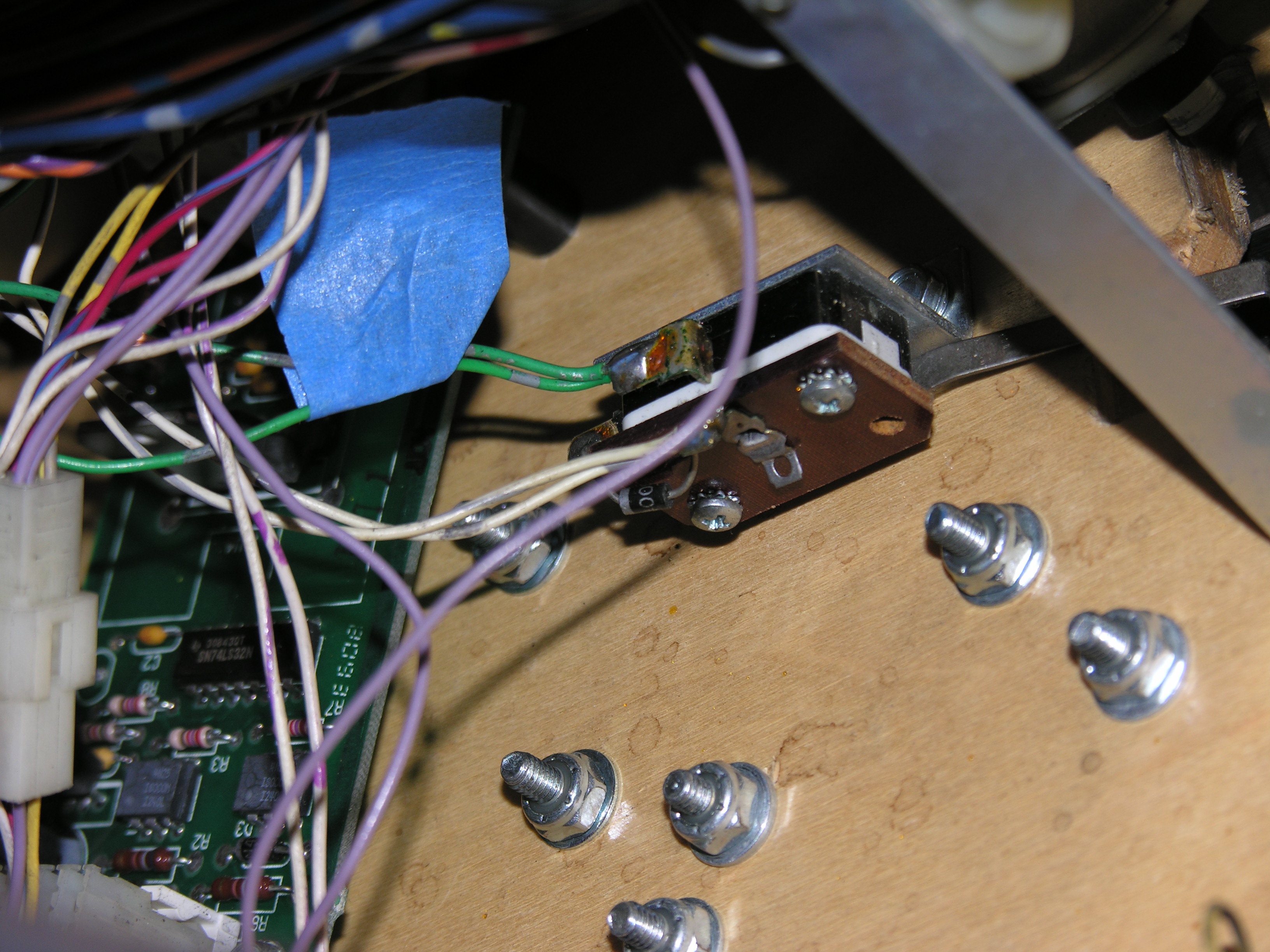
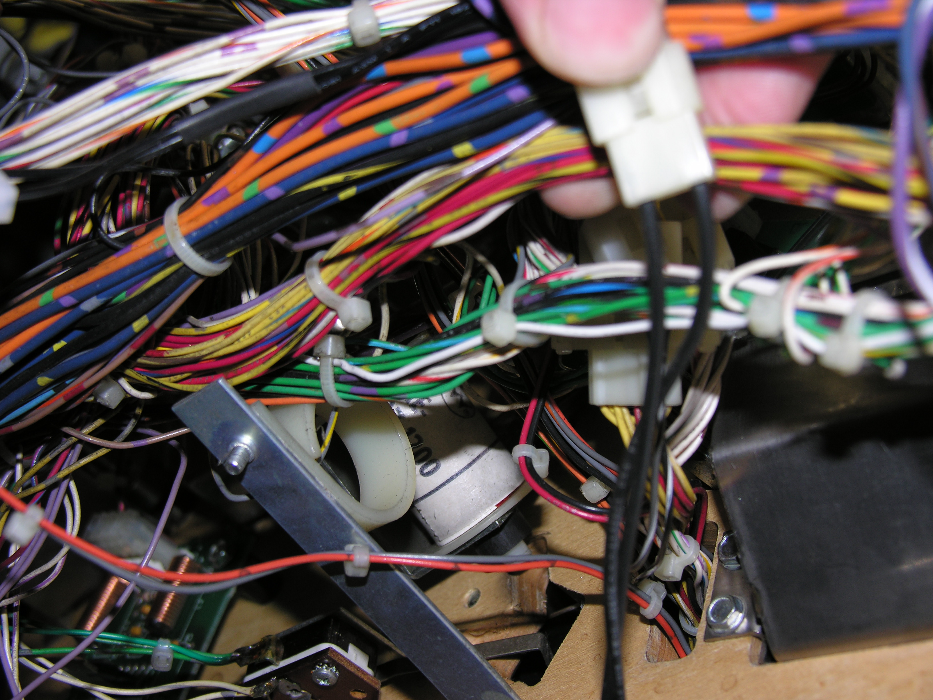
| This is our first attach point, the ball lock switch under the clock area. The blue tape reminds me that we will use the green/grey wire. |
|
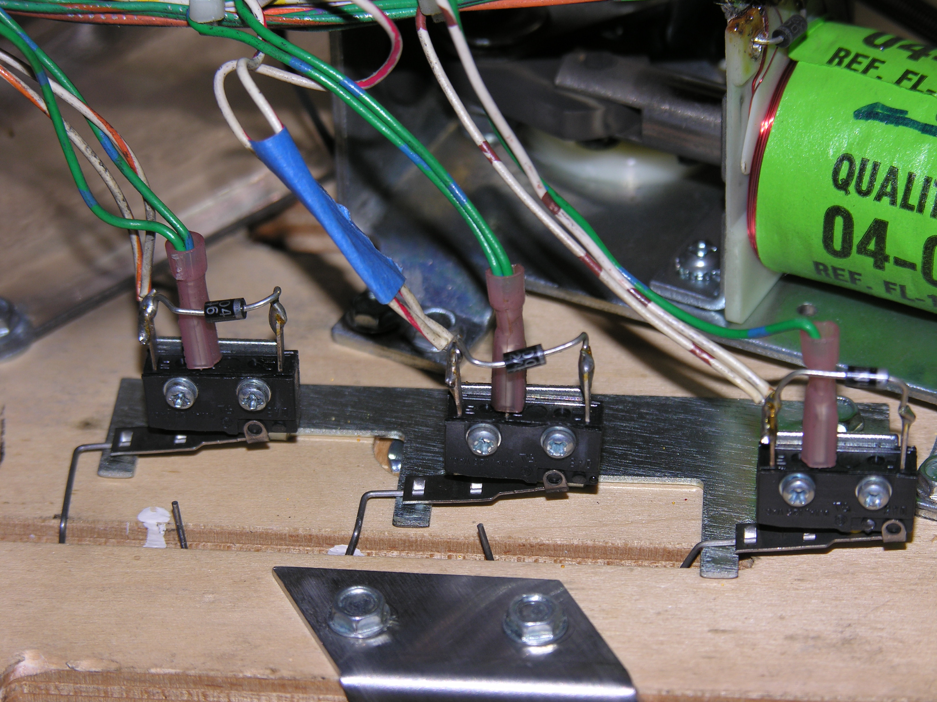
| Here's the other attach point, the orange skill shot switch. This time, we will use the white/red wire. |
|
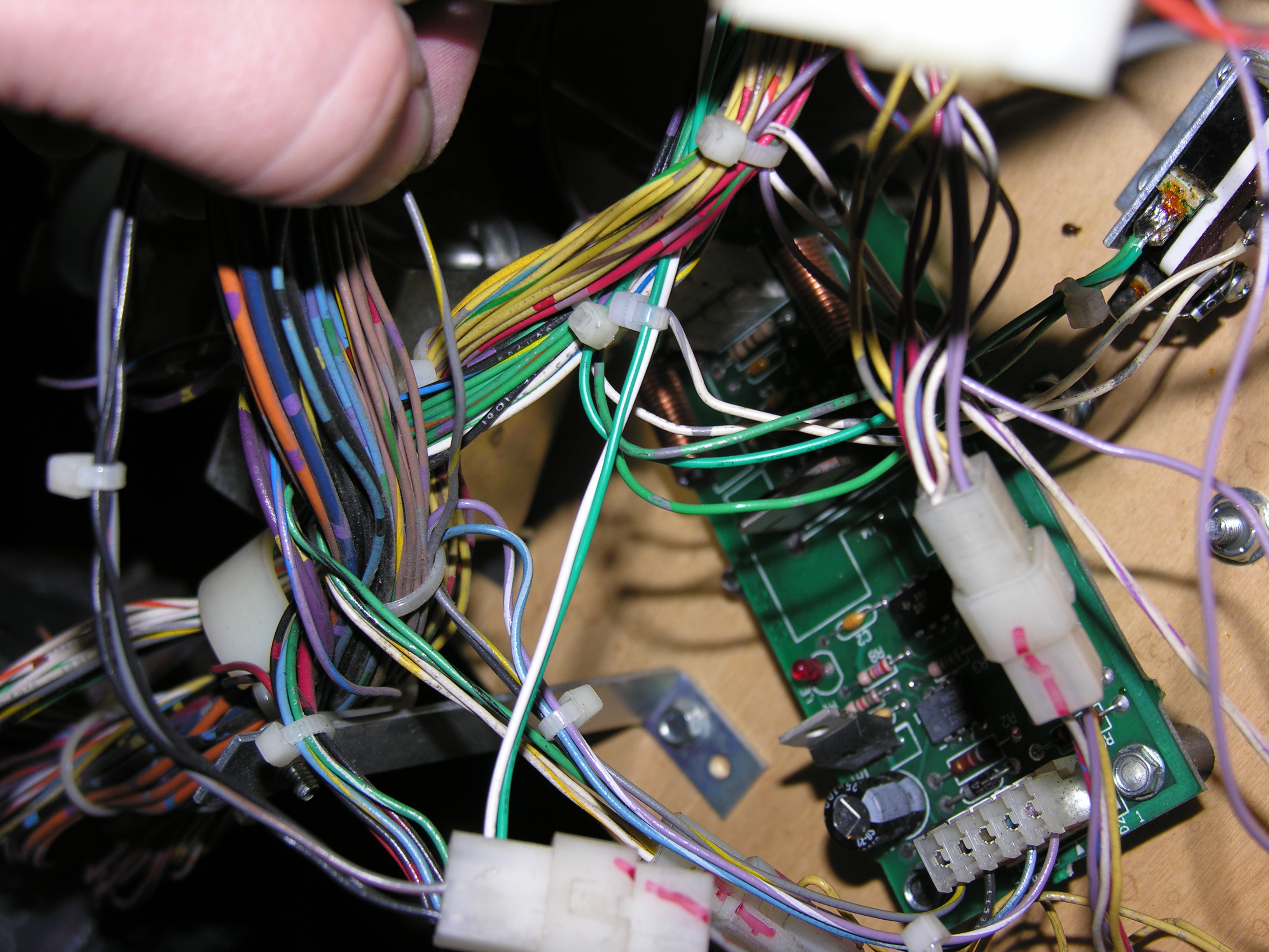
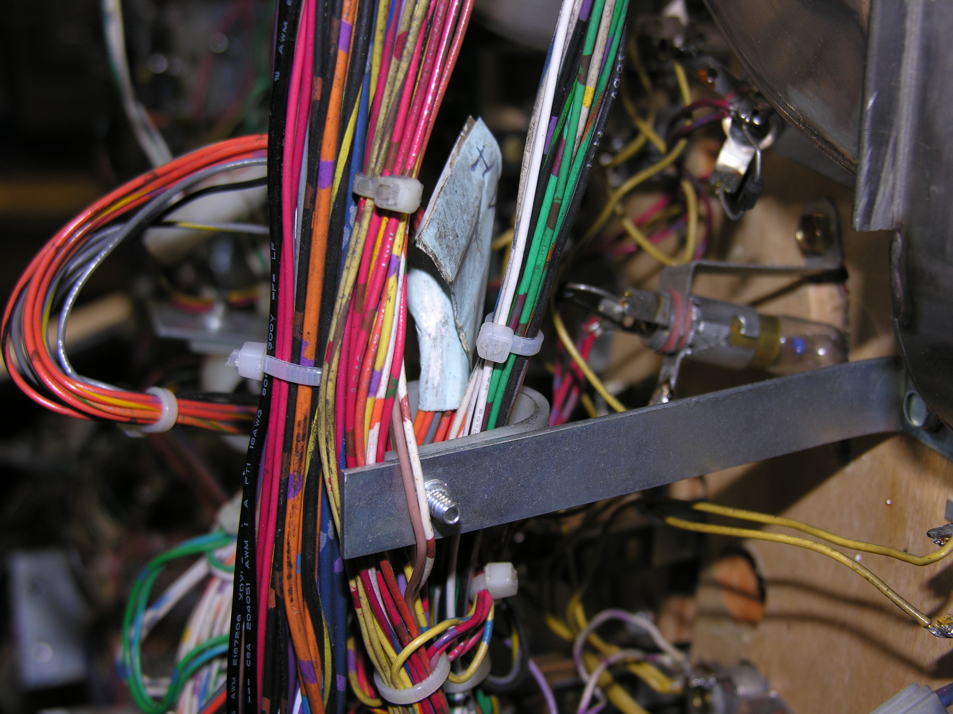
| To make this look neat, you will want to feed the wires through the harness. Mostly, the existing cable ties have enough room to take one more wire. It is easiest to feed the wire just under the clamp, where there is usually a little space. In some places, you will have to replace the tie with a new one. Install a new tie, then remove the old one. | |
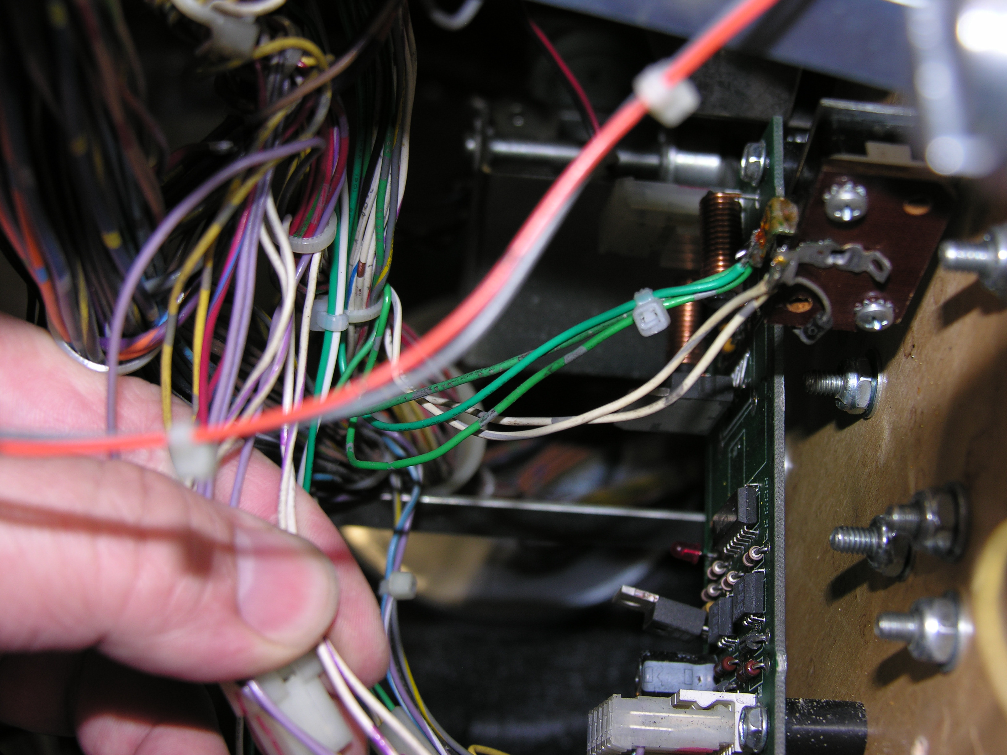
| Here's the new connector, located near the playfield passthrough hole at the top right of the playfield. The new opto receiver connections will come through here and mate with it. |
|
| The green and white wires have a single cable tie on them to keep them straight. |
|
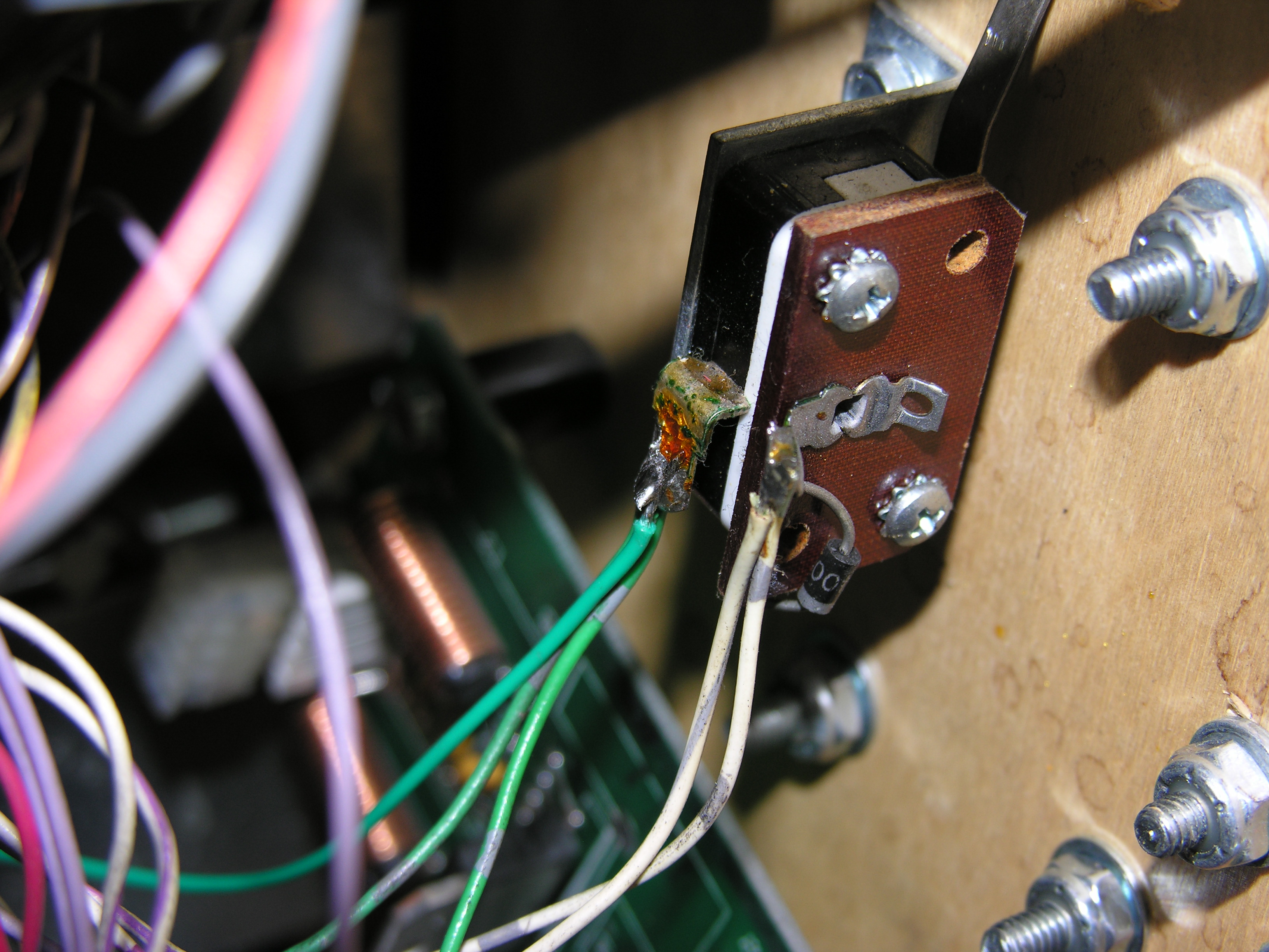
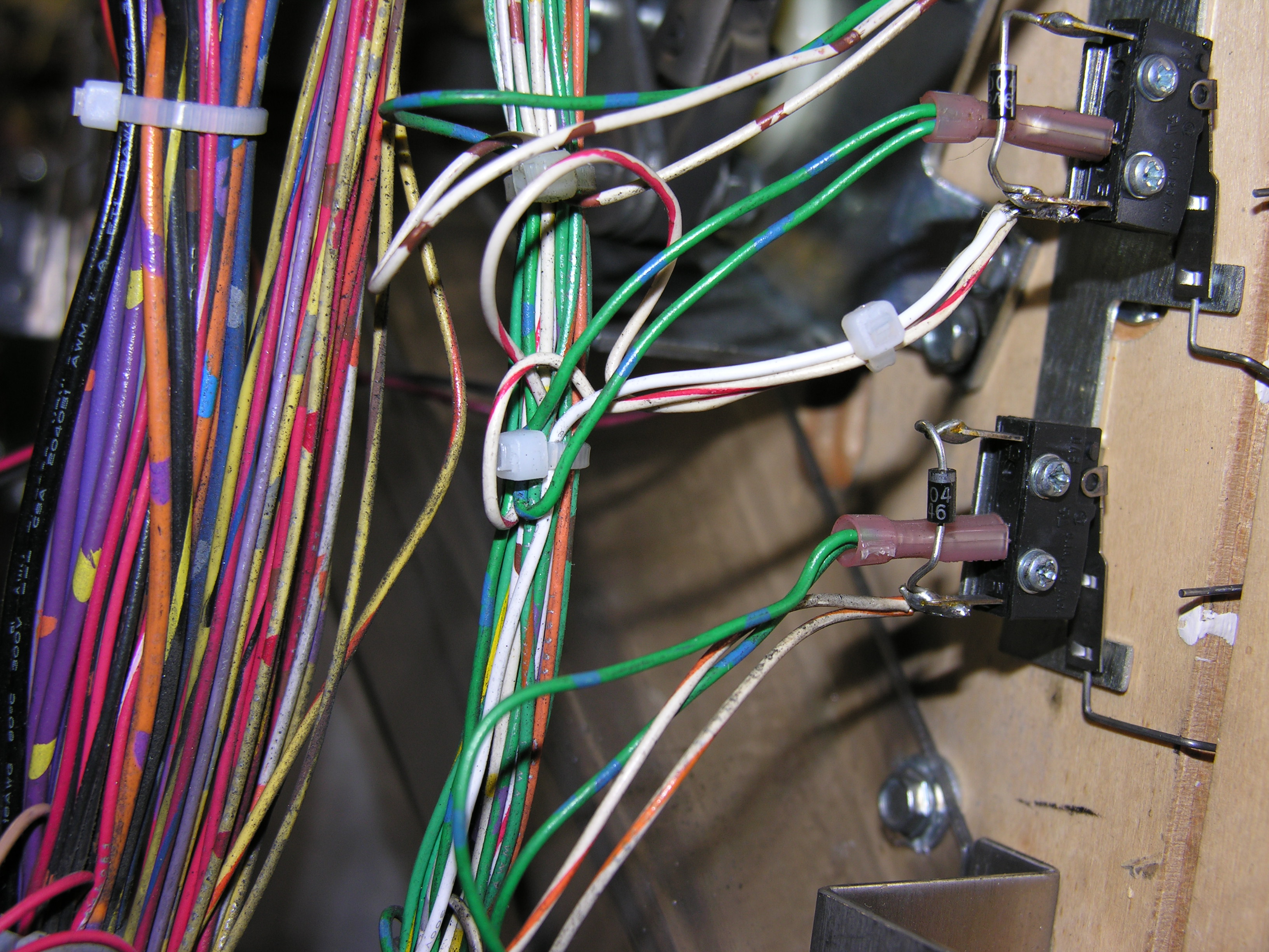
| Here's the green wire going to the green/purple wire on the ball lock switch. Put a cable tie on the three wires to hold them together. Lay the green wire so that it sits on the connection at the switch, then cut it. Strip about 3/16" of wire from the green wire, and solder it onto the joint. Use the other wires and the cable tie to make the wire sit in place on its own, if you can. |
|
| A close-up of the switch. |
|
| Here's the white wire running through the harness. |
|
| The white wire has a longer run. |
|
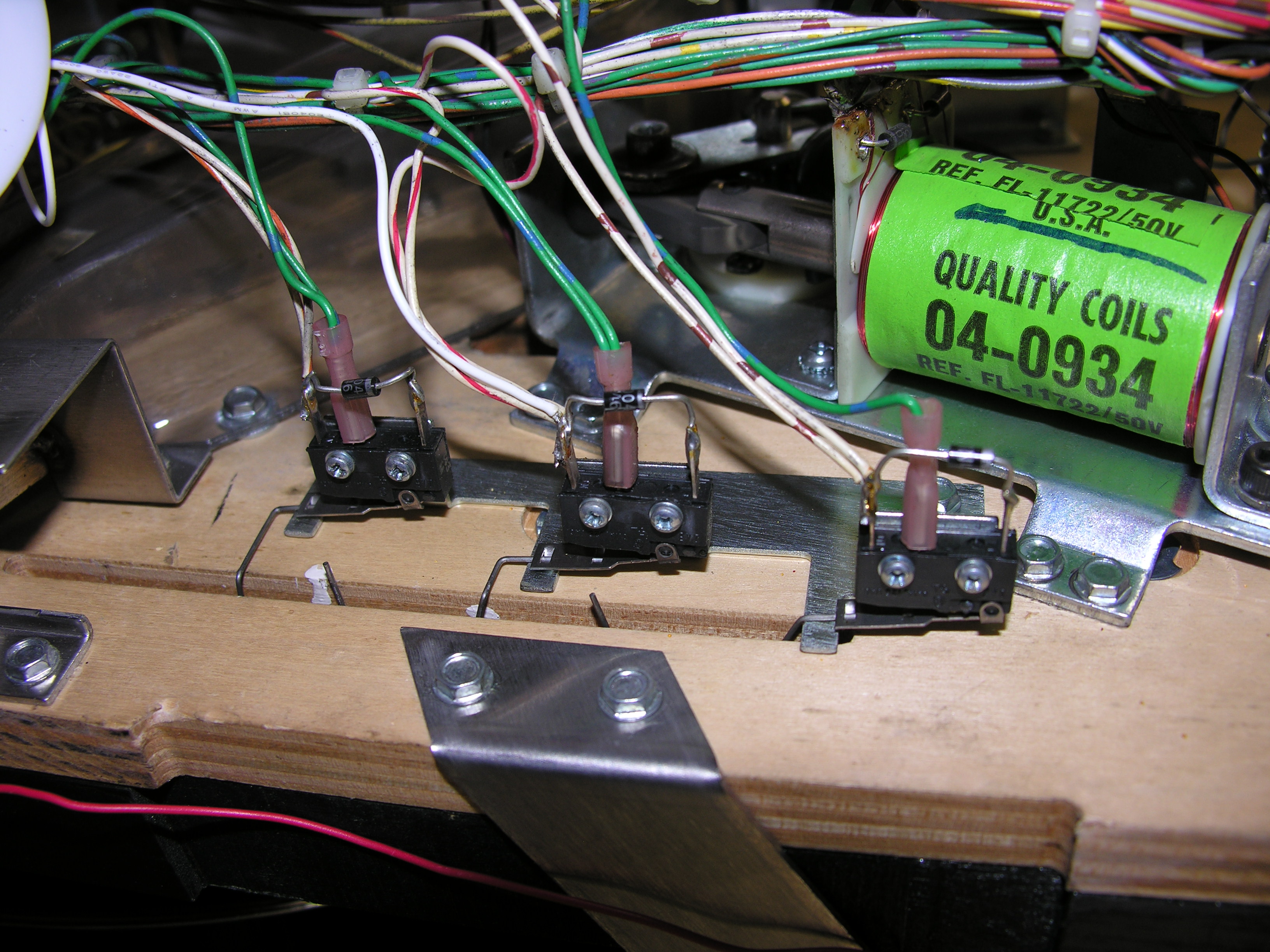
| And here is the connection to the orange skill shot
switch, same process as the green wire.
Once this is soldered, we are done with the soldering iron. |
|
| Here's another view of the white wire connection. |
|
| For the power for the emitter, we tap into the existing
emitter circuit. In this case, we use the IR LED for the lower right
spiral magnet. The normal current for these LEDs is 40mA. The parasitic
circuit takes it down to 35mA.
|
|
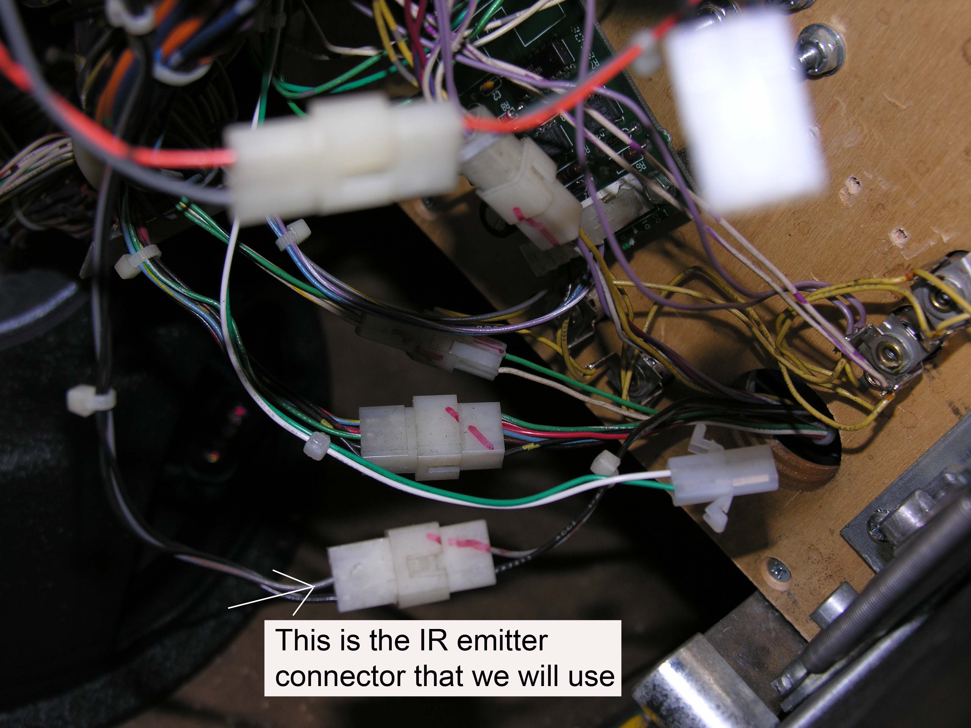
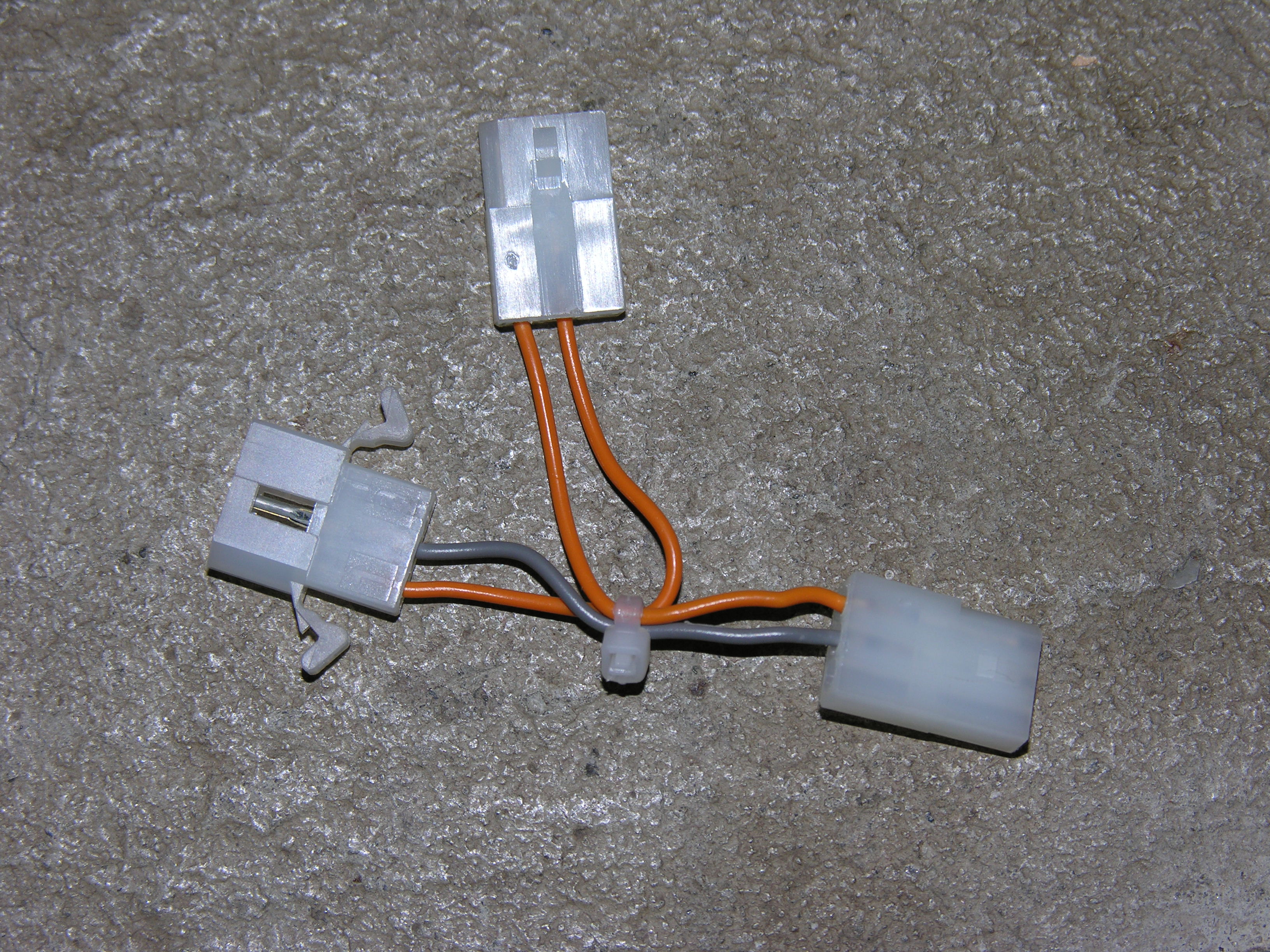
| Here's the parasitic connector. It can only go in one way, and it doesn't matter which arm the emitters connect to. Yours will have black and grey wires. |
|
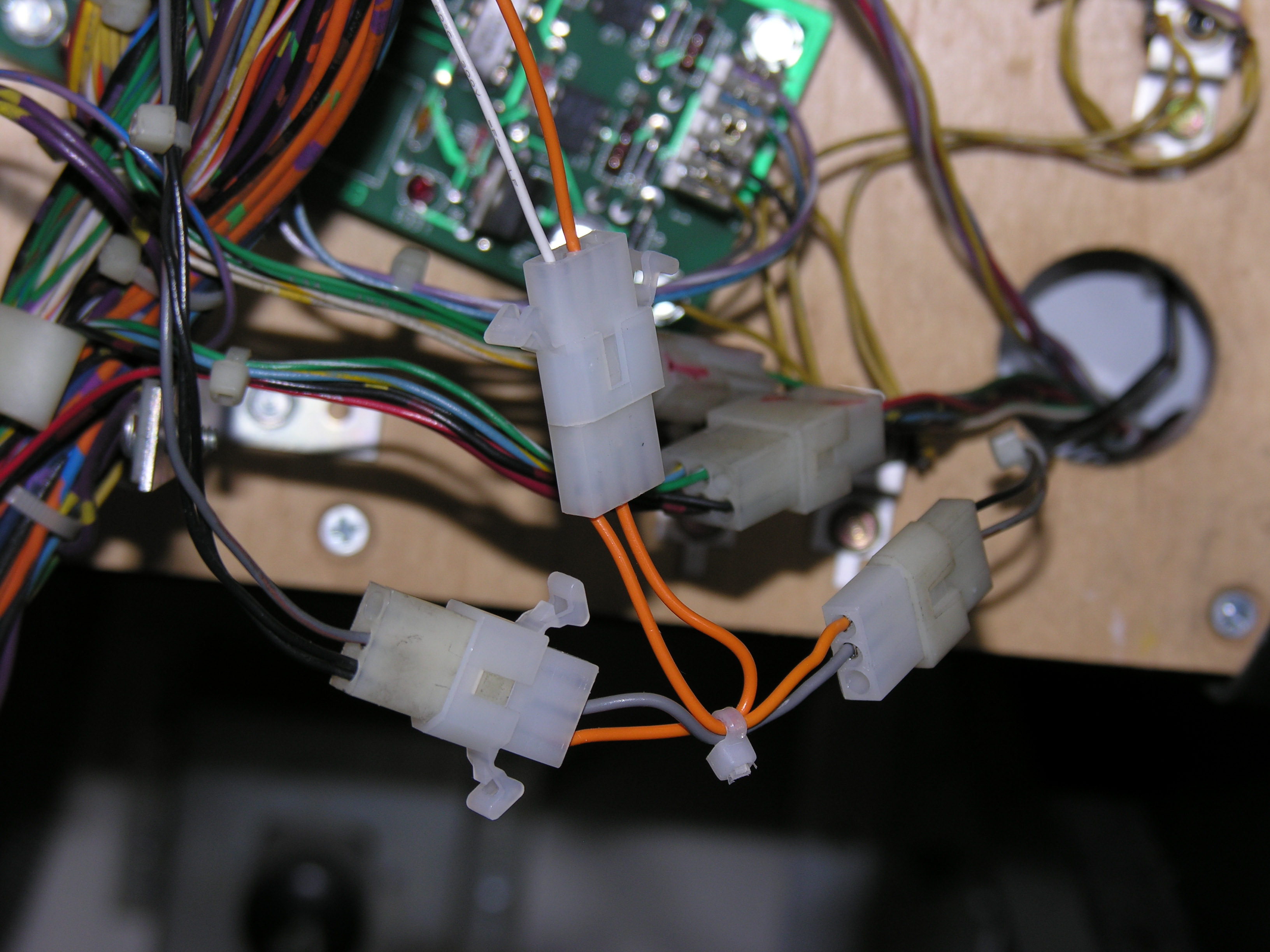
| Installation is easy. Separate the emitter connectors; insert the parasitic harness; rejoin the connector. In this case, my emitter is off on a long cable for testing, but the cable will normally go through the playfield hole. Disconnect this harness if you want to play the machine before you finish the job. Otherwise, your right magnet opto will not work. |
|